


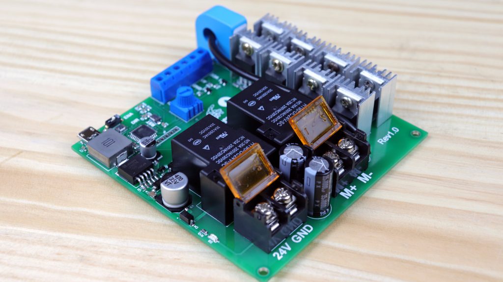

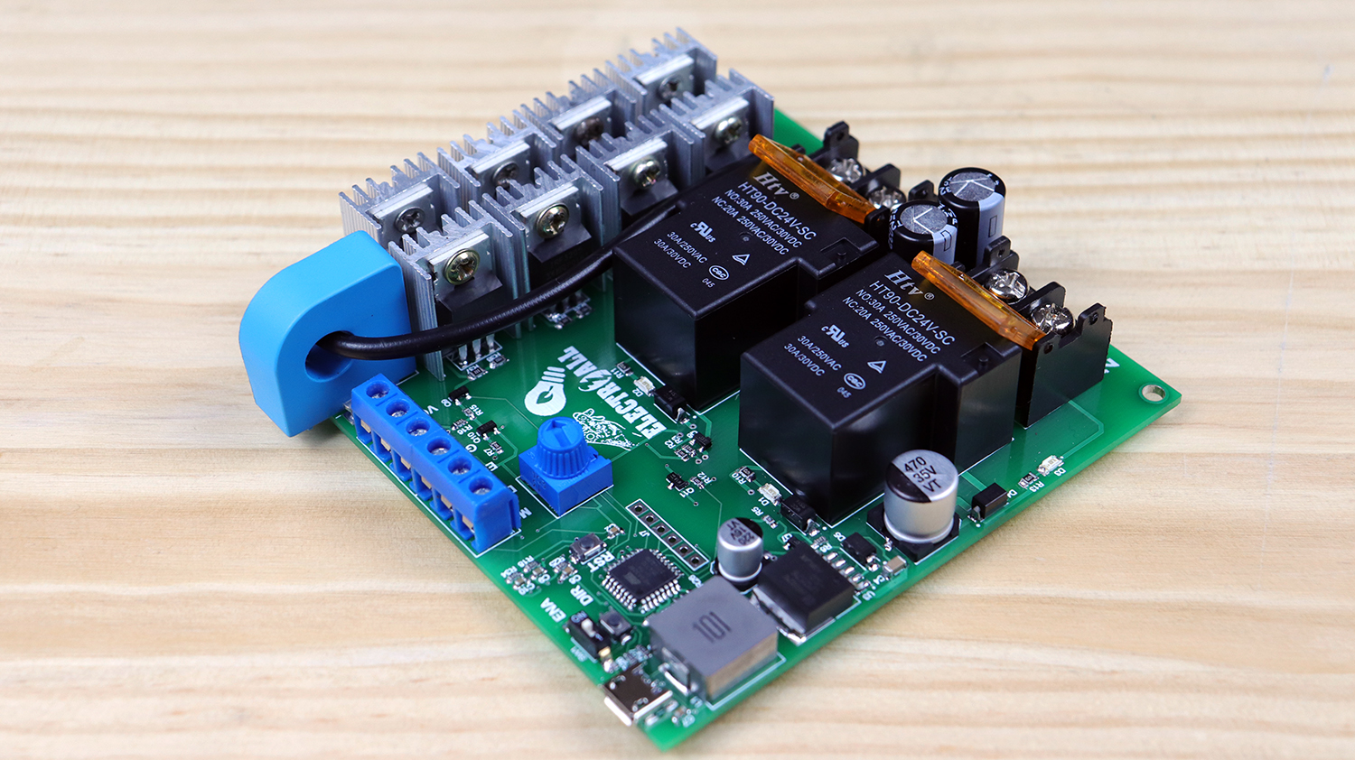
Hace más de tres meses publiqué un video de un controlador de motor de potencia de corriente continua (versión anterior). Sin embargo, dicha versión tenía varios algunos inconvenientes. En primer lugar, para controlar el motor se necesitaba una tarjeta o un microcontrolador externa. En segundo lugar, solo se contaba con 2 mosfets, lo cual no era suficiente para soportar 15A. Viendo todos estos inconvenientes en este video haremos otra versión donde incluiremos un microcontrolador. Además, colocaremos 8 mosfets de manera paralelo para que pueda soportar una mayor cantidad de corriente. Por otro lado, también tendremos un sensor de corriente. finalmente contaremos un switch, un pulsador un potenciómetro para simular el funcionamiento del motor.
ESPECIFICACIONES TÉCNICAS

- Tensión de alimentación……………………….…………24VDC
- Corriente de alimentación………………….……………Depende del consumo del motor
- Entadas digitales nivel TTL 5VDC……………….……2 (ENA, DIR)
- Entrada analógica (potenciómetro)0-5V…………..1
- Salida analógica (sensor corriente “2.5-5V”)……..1
- Programación directa(PC – driver motor)………….Sí
- Condiciones ambientales min……………………….….-10°
- Condiciones ambientales max…………………..……….85°
- Empotrable…………………………………………………………Sí
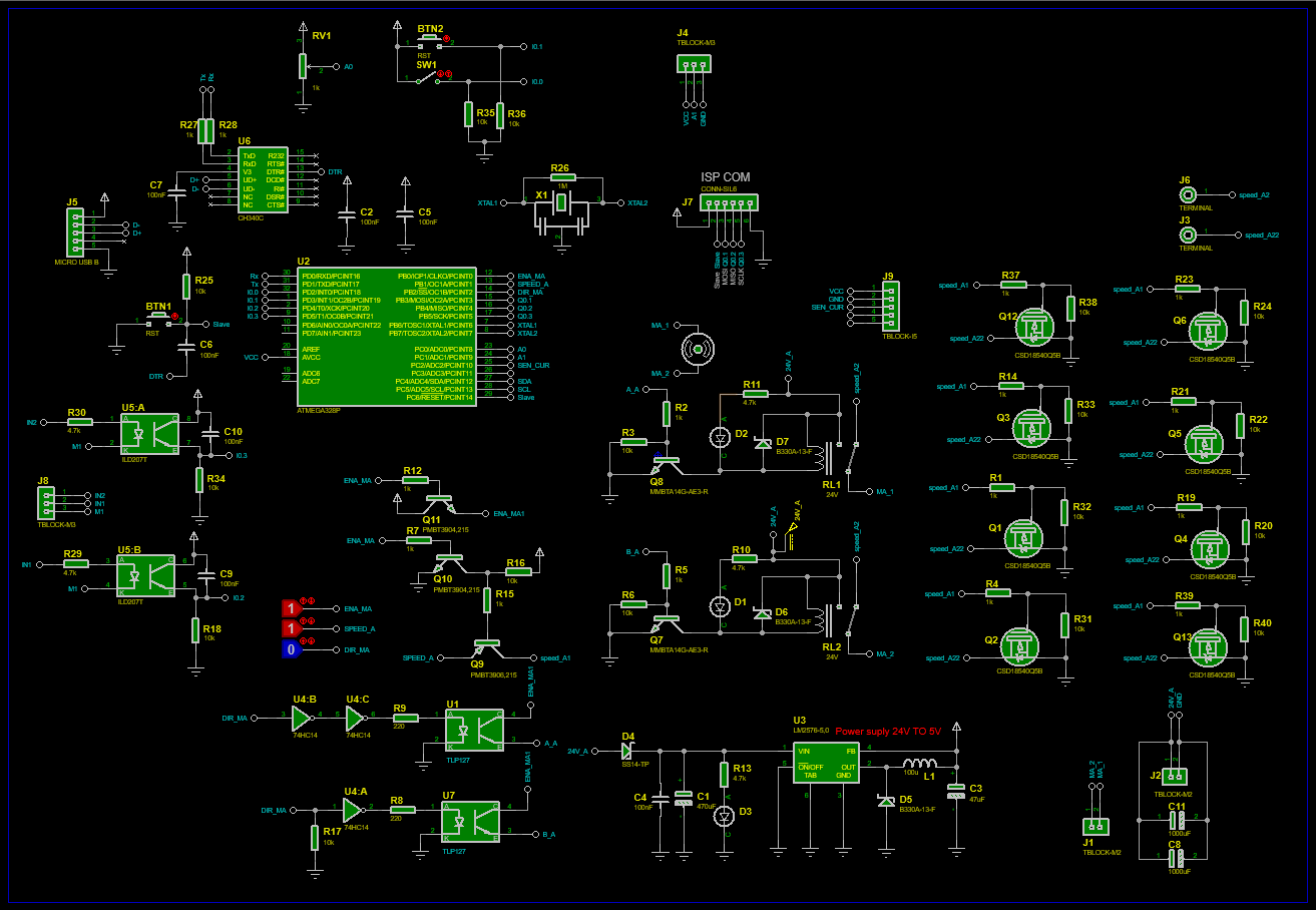
LISTA DE MATERIALES
| Categoría | Cantidad | Referencias | Valor | PCB Package | Datasheet |
| Condensadores | 1 | C1 | 470uF | CAP SMD 10.5X10MM ALUMINUM 470UF/35V | (see & buy) |
| Condensadores | 6 | C2,C5,C6,C7,C9,C10 | 100nF | 0603_CAP | (see & buy) |
| Condensadores | 1 | C3 | 47uF | CAP SMD 6.3X7.7MM ALUMINUM 220UF/16V | (see & buy) |
| Condensadores | 1 | C4 | 100nF | 1206_CAP | (see & buy) |
| Condensadores | 2 | C8,C11 | 1000uF | ELEC-RAD25 | (see & buy) |
| Resistencias | 8 | R1,R4,R14,R19,R21,R23,R37,R39 | 1k | 0805_RES | (see & buy) |
| Resistencias | 7 | R2,R5,R7,R12,R15,R27,R28 | 1k | 0603_RES | (see & buy) |
| Resistencias | 9 | R3,R6,R16,R17,R18,R25,R34,R35,R36 | 10k | 0603_RES | (see & buy) |
| Resistencias | 2 | R8,R9 | 220 | 0603_RES | (see & buy) |
| Resistencias | 3 | R10,R11,R13 | 4.7k | 0805_RES | (see & buy) |
| Resistencias | 8 | R20,R22,R24,R31,R32,R33,R38,R40 | 10k | 0805_RES | (see & buy) |
| Resistencias | 1 | R26 | 1M | 0603_RES | (see & buy) |
| Resistencias | 2 | R29,R30 | 4.7k | 1206_RES | (see & buy) |
| Integrados | 2 | U1,U7 | PC817 | SOIC250P670X300-4 | (see & buy) |
| Integrados | 1 | U2 | ATMEGA328P | QFP80P900X900X120-32 | (see & buy) |
| Integrados | 1 | U3 | LM2576-5,0 | TO170P1410X464-6 | (see & buy) |
| Integrados | 1 | U4 | 74HC14 | SO14 | (see & buy) |
| Integrados | 1 | U5 | ILD207T | SO8 | (see & buy) |
| Integrados | 1 | U6 | CH340C | SO16 | (see & buy) |
| Transistores | 8 | Q1,Q2,Q3,Q4,Q5,Q6,Q12,Q13 | CSD18540Q5B | TO220 | (see & buy) |
| Transistores | 2 | Q7,Q8 | MMBTA14G-AE3-R | SOT23-3 | (see & buy) |
| Transistores | 1 | Q9 | PMBT3906,215 | SOT23-3 | (see & buy) |
| Transistores | 2 | Q10,Q11 | PMBT3904,215 | SOT23-3 | (see & buy) |
| Diodos | 2 | D1,D2 | LED-RED | LEDC3216X110 | (see & buy) |
| Diodos | 1 | D3 | LED-GREEN | LEDC3216X110 | (see & buy) |
| Diodos | 1 | D4 | SS14-TP | DIOM5226X230N | (see & buy) |
| Diodos | 3 | D5,D6,D7 | B330A-13-F | DIOM5226X230N | (see & buy) |
| Miscelánea | 2 | BTN1,BTN2 | RST | BUTTON SMD 2P | (see & buy) |
| Miscelánea | 2 | J1,J2 | TBLOCK-M2 | TERMINAL BLOCKS DIBO | (see & buy) |
| Miscelánea | 2 | J3,J6 | TERMINAL | JUMPER MOTOR CONTROL | cable |
| Miscelánea | 2 | J4,J8 | TBLOCK-M3 | T-BLOCK 3PIN GREEN | (see & buy) |
| Miscelánea | 1 | J5 | MICRO USB B | MICRO USB B | (see & buy) |
| Miscelánea | 1 | J7 | CONN-SIL6 | CONN-SIL6 | |
| Miscelánea | 1 | J9 | TBLOCK-I5 | CURENT SENSOR | (see & buy) |
| Miscelánea | 1 | L1 | 100u | INDUCTOR 100UH | (see & buy) |
| Miscelánea | 2 | RL1,RL2 | 24V | RELAY 24VDC-SL-A | (see & buy) |
| Miscelánea | 1 | RV1 | 1k | POTENCIOMETER MANU SMALL | (see & buy) |
| Miscelánea | 1 | SW1 | DIPSWITCH SMD 1P | (see & buy) | |
| Miscelánea | 1 | X1 | CRYSTAL SMD S | OSCILADOR SMD CERAMIC RESONATORS | (see & buy) |
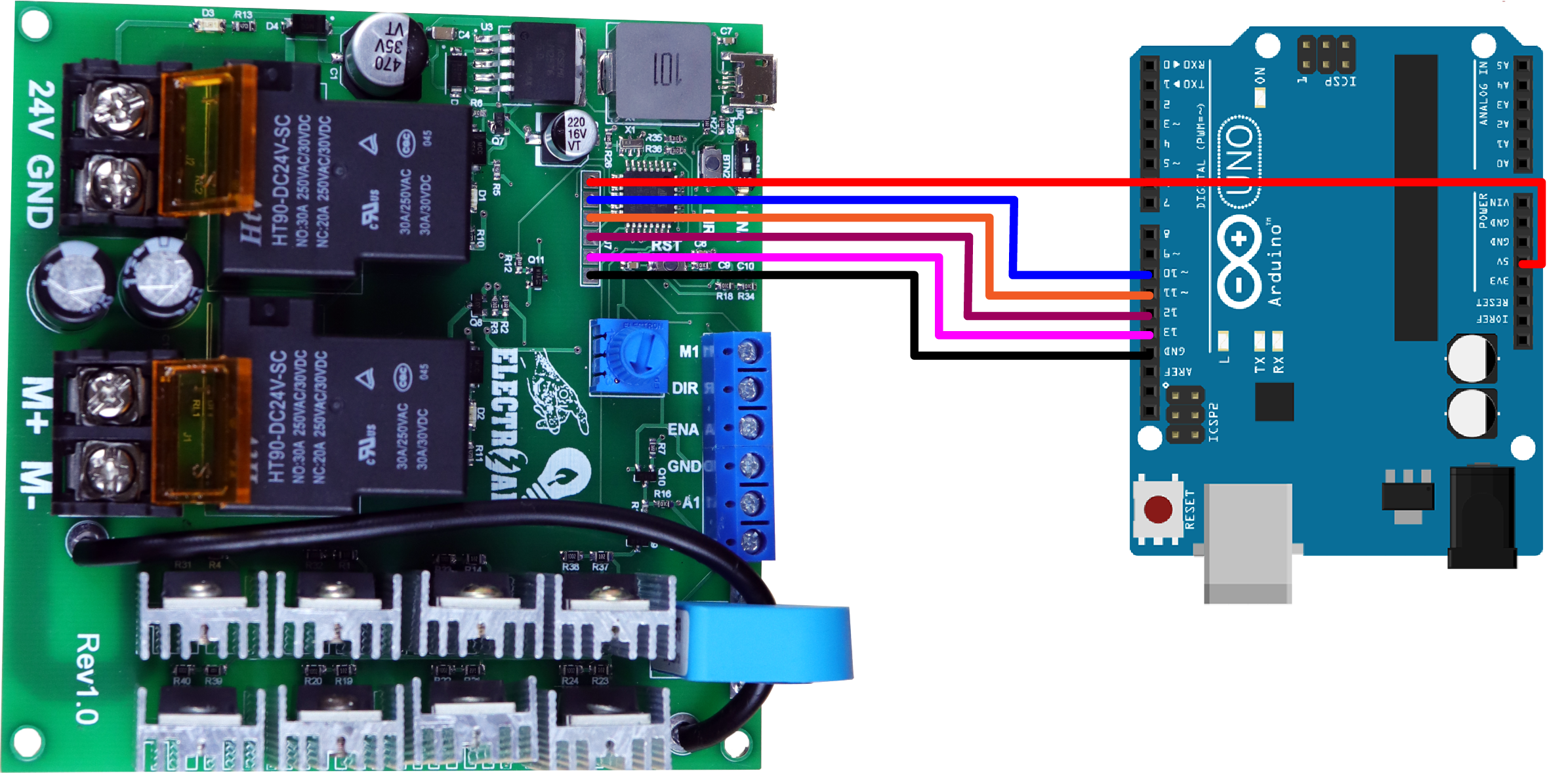
CONEXIONES EXTERNAS
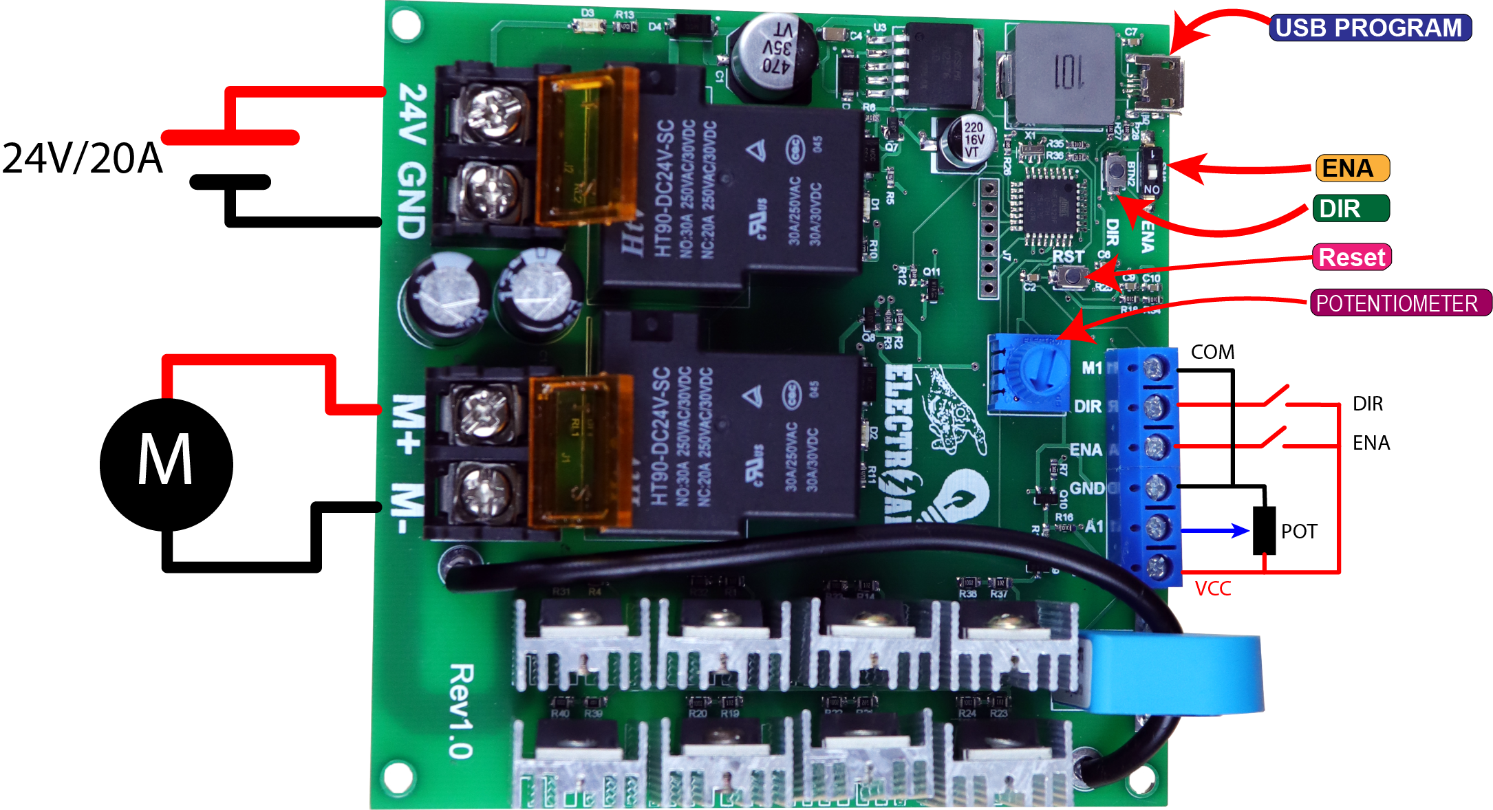
CONEXIONES ARDUINO – MOTOR DRIVER
PASO 1 : SUBIR GESTOR DE ARRANQUE (BOOTLOADER)
Para poder usar un microcontrolador nuevo (atmega328P-AU), es necesario subir un un gestor de arranque como también llamado “BOOTLOADER”, esto nos facilitará subir programas en futuras ocasiones.
finalmente para quemar el bootloader se tendrá que realizar a través de los pines ICSP, que prácticamente serían los pines [ (MOSI=11) (MISO = PIN12) (SCK=PIN13) (Slave=PIN10) ]. Para subir y quemar el gestor de arranque necesitaremos un arduino UNO ó MEGA y realizar las siguientes conexiones (ARDUINO UNO – DRIVER).
PASO 2 : SUBIR PROGRAMA; PC – DRIVER
Después de haber subido el gestor de arranque finalmente ya podremos subir cualquier programa como normalmente lo realizamos a través del puerto serie.
CODIGO ARDUINO
const int in_ena = 2; // pin2 switch dentro de la placa    ||| pin5 switch externo
const int in_dir = 3; // pin3 pulsador dentro de la placa  ||| pin4 pulsador externo
const int ENA = 8;
const int PWM = 9;
const int DIR = 10;
boolean state_dir = false;
boolean state_slow = false;
boolean state_vel = false;
byte slow = 0;
int valor1 = 0;
int valor2 = 0;
void setup() {
  Serial.begin(9600);
  pinMode(in_ena, INPUT);
  pinMode(in_dir, INPUT);
  pinMode (ENA, OUTPUT);
  pinMode (PWM, OUTPUT);
  pinMode (DIR, OUTPUT);
  digitalWrite(ENA, 0);
  digitalWrite(DIR, 0);
}
void loop() {
  int ana ;
  int map_ana ;
  if (digitalRead(in_ena) == 1 ) digitalWrite(ENA, 1);
  else digitalWrite(ENA, 0);
  if (state_vel == false) {
    ana = analogRead(A0);  // A0 Potenciometro dentro de la placa || A1 Ponteciometro externo.
    map_ana = map(ana, 0, 1023, 0, 255);
    slow = map_ana;
  }
  if (digitalRead(in_dir) && valor1 == 0 ) {
    delay(100);
    valor2 = 1 - valor2;
  }
  valor1 = digitalRead(in_dir);
if(digitalRead(in_dir)==1){
  if (valor2 == 1) {
    state_vel = true;
    if (state_vel == true) {
      analogWrite(PWM, 0);
      delay(1000);
      digitalWrite(DIR, 1);
      slow=0;
    for(int i=0;i<=map_ana;i++ ){
      slow++;
      delay(10);
      Serial.println(slow);
      analogWrite(PWM, slow);
    }
    if (slow >= map_ana) {
      state_vel = false;
    }
    }
  }
  }
if(digitalRead(in_dir)==1){
   if (valor2 == 0) {
    state_vel = true;
    if (state_vel == true) {
      analogWrite(PWM, 0);
      delay(1000);
      digitalWrite(DIR, 0);
      slow=0;
    for(int i=0;i<=map_ana;i++ ){
      slow++;
      delay(10);
      Serial.println(slow);
      analogWrite(PWM, slow);
    }
    if (slow >= map_ana) {
      state_vel = false;
    }
    }
  }
  }
    analogWrite(PWM, slow);
}
