


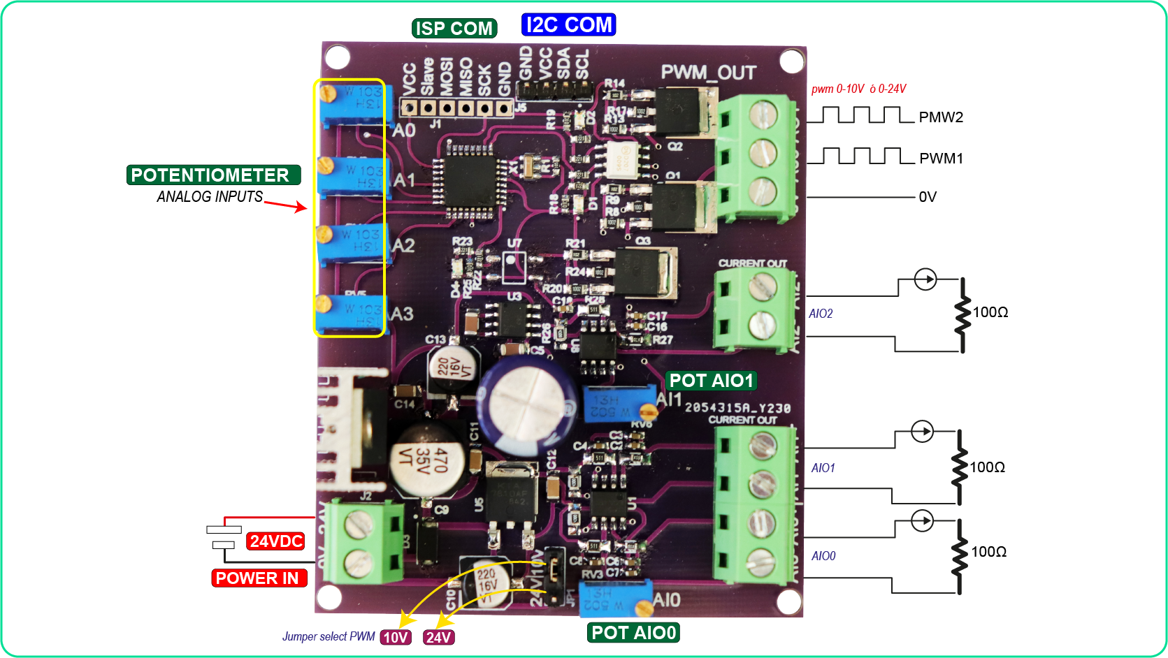
Hace un tiempo atrás publique un video sobre una tarjeta conversor de corriente a voltaje, en dicho video muchas personas me solicitaban que creara un circuito que hiciera lo contrario, es decir, que convierta señales de corriente a voltaje. En efecto, hoy crearemos 3 fuentes de corriente de 4-20mA. Además, se creará generadores de modulación por ancho de pulso(PWM), que oscilará entre 0 a 10V y 0 a 24V, los cuales se regularán mediante unos potenciómetros
DATOS TÉCNICOS

- Tensión de alimentación……………………….…………24VDC
- Corriente de alimentación………………….……………150mA
- Entadas Analógicas (0-5V)……………….……………….4
- Programación ISP……………………..………………………..Sí
- Comunicación I2C………………………………………………….Sí
- Salida PWM 0-10V ó 0-24V…………………………………..2
- Salida corriente 0-20mA…………………………………………3
- Condiciones ambientales min……………………….….-10°
- Condiciones ambientales max…………………..……….85°

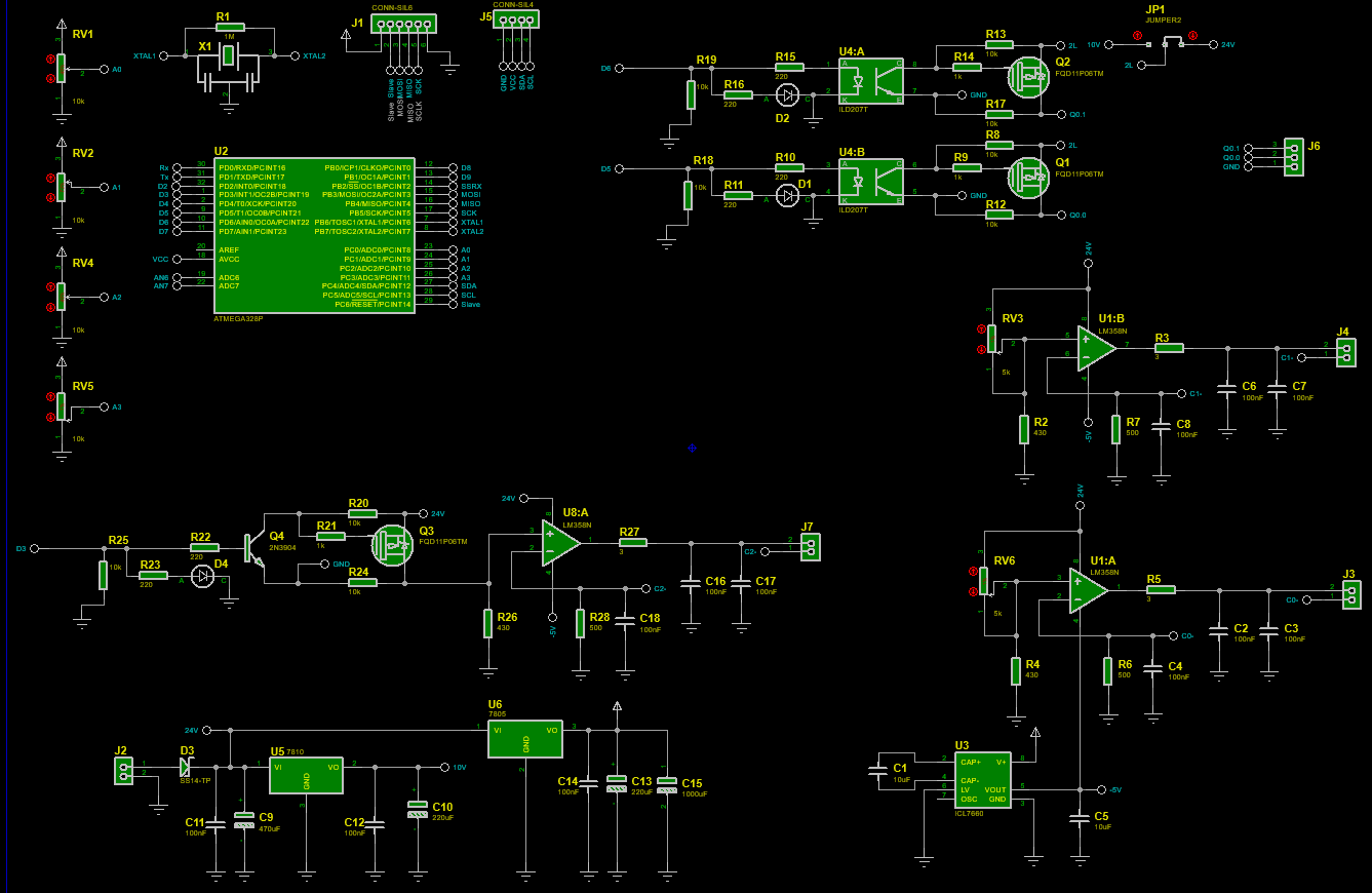
LISTA DE MATERIALES
| Categoría | Cantidad | Referencias | Valor | PCB Package | Datasheet |
| Condensadores | 2 | C1,C5 | 10uF | 1206_CAP | (see & buy) |
| Condensadores | 9 | C2,C3,C4,C6,C7,C8,C16,C17,C18 | 100nF | 0603_CAP | (see & buy) |
| Condensadores | 1 | C9 | 470uF | CAP SMD 10.5X10MM ALUMINUM 470UF/35V | (see & buy) |
| Condensadores | 2 | C10,C13 | 220uF | CAP SMD 6.3X7.7MM ALUMINUM 220UF/16V | (see & buy) |
| Condensadores | 3 | C11,C12,C14 | 100nF | 1206_CAP | (see & buy) |
| Condensadores | 1 | C15 | 1000uF | ELEC-RAD25 | (see & buy) |
| Resistencias | 1 | R1 | 1M | 0603_RES | (see & buy) |
| Resistencias | 3 | R2,R4,R26 | 430 | 1206_RES | (see & buy) |
| Resistencias | 3 | R3,R5,R27 | 3 | 1206_RES | (see & buy) |
| Resistencias | 3 | R6,R7,R28 | 500 | 1206_RES | (see & buy) |
| Resistencias | 6 | R8,R12,R13,R17,R20,R24 | 10k | 0805_RES | (see & buy) |
| Resistencias | 3 | R9,R14,R21 | 1k | 0805_RES | (see & buy) |
| Resistencias | 6 | R10,R11,R15,R16,R22,R23 | 220 | 0603_RES | (see & buy) |
| Resistencias | 3 | R18,R19,R25 | 10k | 0603_RES | (see & buy) |
| Integrados | 2 | U1,U8 | LM358N | SO8 | (see & buy) |
| Integrados | 1 | U2 | ATMEGA328P | QFP80P900X900X120-32 | (see & buy) |
| Integrados | 1 | U3 | ICL7660 | SO8 | (see & buy) |
| Integrados | 1 | U4 | ILD207T | SO8 | (see & buy) |
| Integrados | 1 | U5 | 7810 | DPAK-N | (see & buy) |
| Integrados | 1 | U6 | 7805 | P1 | (see & buy) |
| Transistores | 3 | Q1,Q2,Q3 | FQD11P06TM | DPAK-N | (see & buy) |
| Transistores | 1 | Q4 | 2N3904 | TO92 | (see & buy) |
| Diodos | 3 | D1,D2,D4 | LED-RED | LEDC2012X120 | (see & buy) |
| Diodos | 1 | D3 | SS14-TP | DIOM5226X230N | (see & buy) |
| Miscelánea | 1 | J1 | CONN-SIL6 | CONN-SIL6 | (see & buy) |
| Miscelánea | 4 | J2,J3,J4,J7 | TBLOCK-M2 | T-BLOCK 2PIN BLUE | (see & buy) |
| Miscelánea | 1 | J5 | CONN-SIL4 | CONN-SIL4 | (see & buy) |
| Miscelánea | 1 | J6 | TBLOCK-M3 | T-BLOCK 3PIN BLUE | (see & buy) |
| Miscelánea | 1 | JP1 | JUMPER2 | CONN-SIL3 | (see & buy) |
| Miscelánea | 4 | RV1,RV2,RV4,RV5 | 10k | PRE-VMT | (see & buy) |
| Miscelánea | 2 | RV3,RV6 | 5k | PRE-VMT | (see & buy) |
| Miscelánea | 1 | X1 | CRYSTAL SMD S | OSCILADOR SMD CERAMIC RESONATORS | (see & buy) |
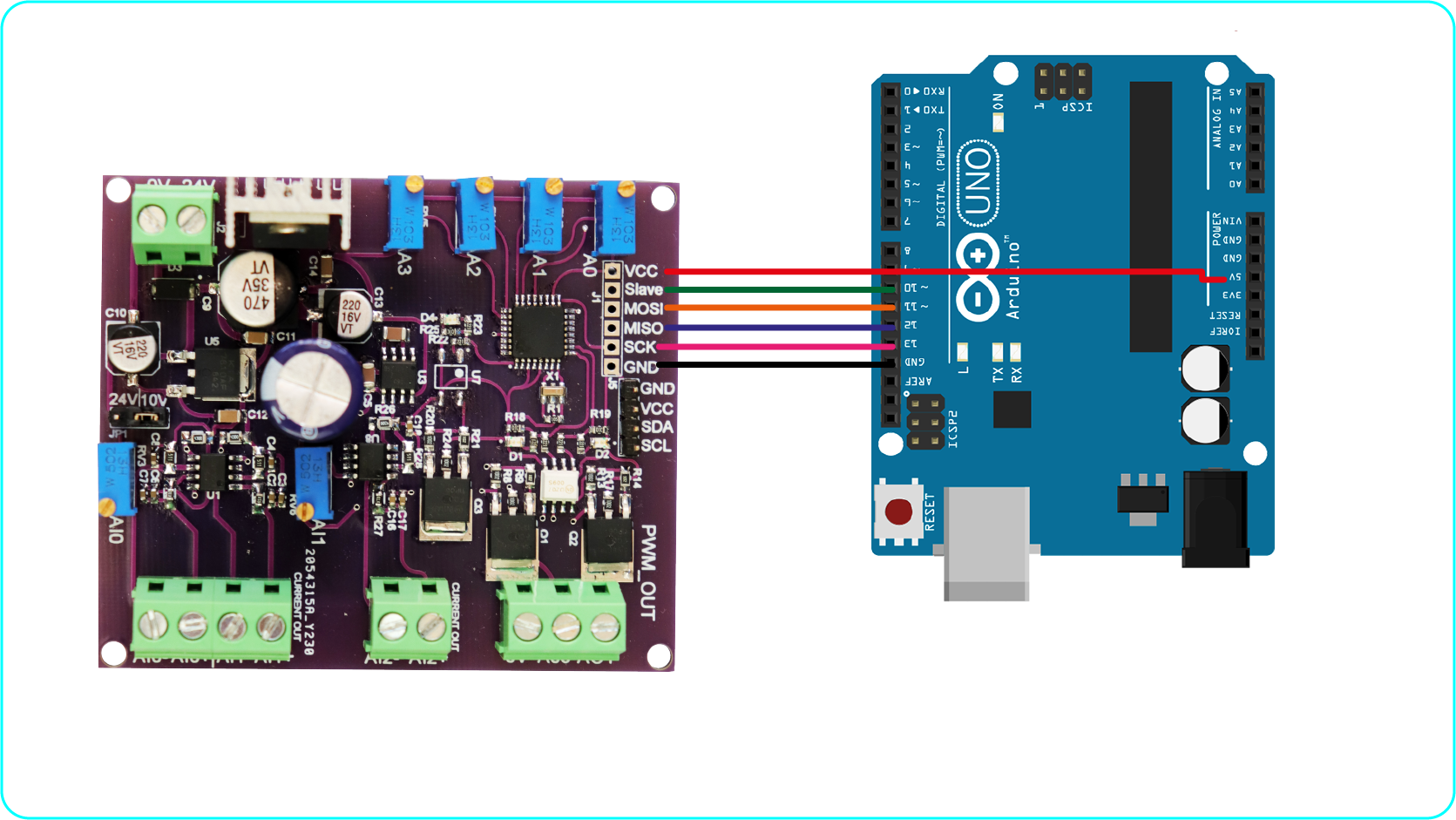
CONEXIONES EXTERNAS
SUBIR BOOTLOADER
Para poder usar un microcontrolador nuevo (atmega328P), es necesario subir un un gestor de arranque como también llamado “BOOTLOADER”, esto nos facilitará subir programas en futuras ocasiones.
finalmente para quemar el bootloader se tendrá que realizar a través de los pines ICSP, que prácticamente serían los pines [ (MOSI=PIN11) (MISO = PIN12) (SCK=PIN13) (Slave=PIN10) ]. Para subir y quemar el gestor de arranque necesitaremos un arduino UNO ó MEGA y realizar las siguientes conexiones (ARDUINO UNO – BOARD).
CODIGOS DE PRUEBA (arduino)
int pwm11 = 3;
int pwm22 = 5;
int pwm33 = 6;

void setup() {
  pinMode(pwm11, OUTPUT);
  pinMode(pwm22, OUTPUT);
  pinMode(pwm33, OUTPUT);
}

void loop() {
  int pwm1 = map(analogRead(A2), 1023, 0, 255, 0);
  analogWrite(pwm11, pwm1);

  int pwm2 = map(analogRead(A1), 1023, 0, 255, 0);
  analogWrite(pwm22, pwm2);

  int pwm3 = map(analogRead(A0), 1023, 0, 255, 0);
  analogWrite(pwm33, pwm3);

}