Contenidos
ocultar
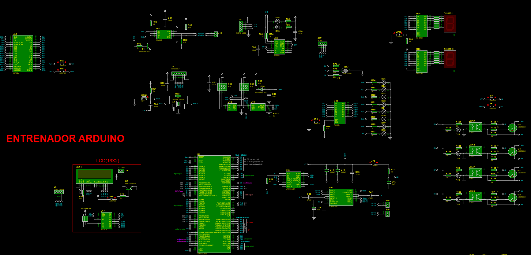
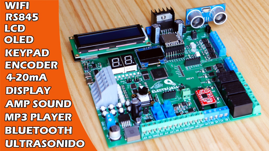
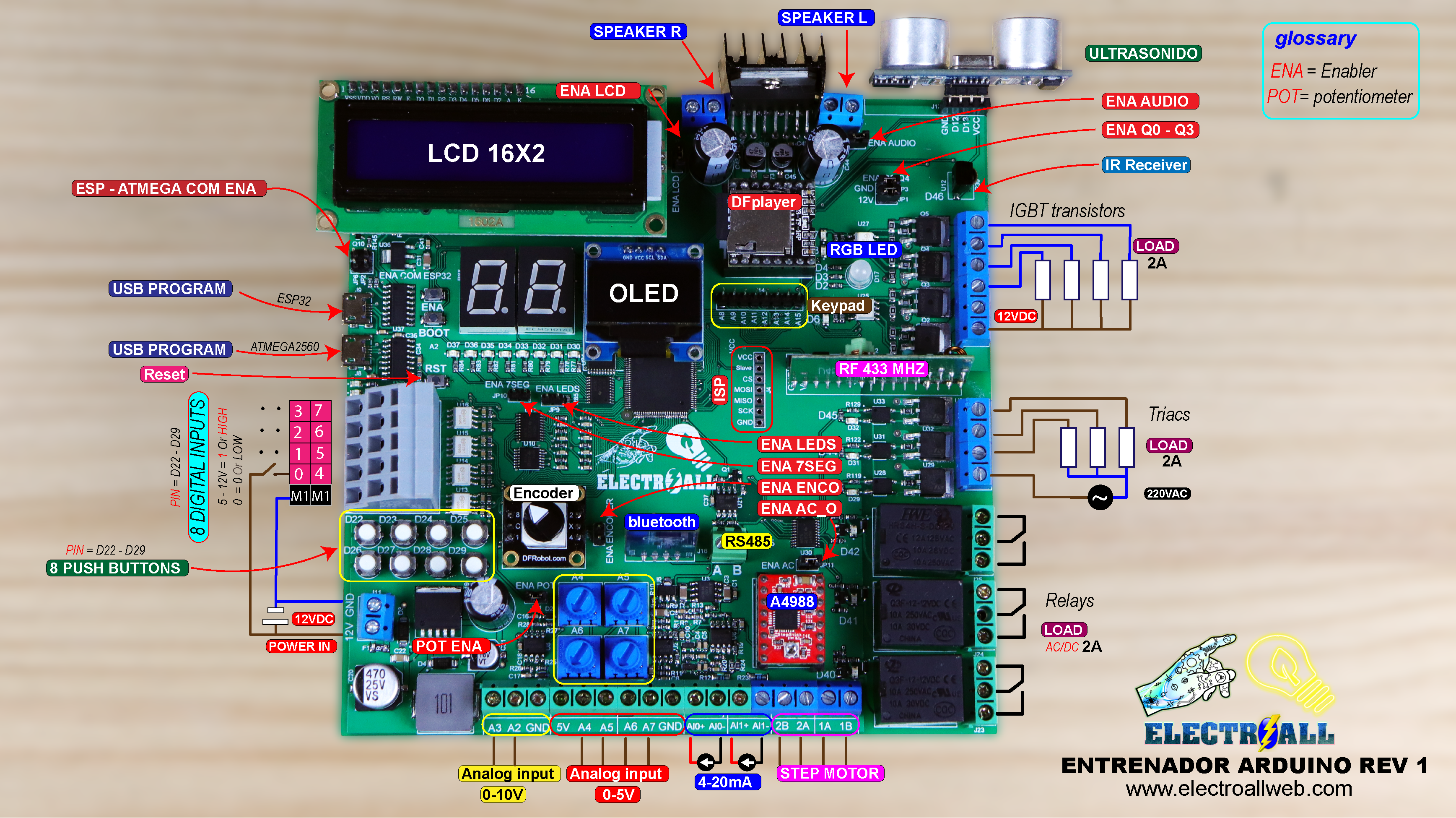
Arto de realizar conexiones cableadas cuando se requiere trabajar con las tarjetas de arduino, sensores, módulos y componentes externos? pues no te preocupes, hoy crearemos una tarjeta PCB completo que incorpore la mayoría de sensores y módulos que se trabaja con arduino, tales como; ESP32 que nos sirve para una comunicación wifi, modulo bluetooth, reloj de tiempo real, reproductor de música y su respectivo amplificador de sonido estéreo hasta 35W, pantalla LCD, pantalla OLED, entradas digitales de 5-12V con sus respectivos pulsadores, teclado matricial de 4*4, control remoto de RF de 433Mhz, sensor ultrasonido, encoder de 4bits, entradas analógicas de corriente (4-20mA), entradas analógicas de voltaje de 0-5V y de 0-10V con potenciómetro incorporado, led RGB, 8bits de leds normales, display de 7 segmentos, salidas a transistores IGBT, salidas a triac para controlar corriente alterna, salidas a relay, salida para motor paso a paso y muchas opciones más. Considero que lo más importante es poder poder subir cualquier programa de manera directa (ordenador – tarjeta entrenadora).
| Categoría | Cantidad | Referencias | Valor | PCB Package | Datasheet |
| Condensadores | 31 | C1,C4,C5,C6,C7,C8,C10,C11,C12, C13,C14,C15,C16,C17,C18,C23, C24,C25,C26,C27,C28,C29,C30, C32,C33,C34,C35,C36,C37,C38,C41 |
100nF | 0603_CAP | (see & buy) |
| Condensadores | 5 | C2,C3,C9,C31,C47 | 10uF | 1206_CAP | (see & buy) |
| Condensadores | 3 | C19,C43,C44 | 1000uF | ELEC-RAD25 | (see & buy) |
| Condensadores | 1 | C20 | 470uF | CAP SMD 10.5X10MM ALUMINUM 470UF/35V | (see & buy) |
| Condensadores | 1 | C21 | 220uF | CAP SMD 6.3X7.7MM ALUMINUM 220UF/16V | (see & buy) |
| Condensadores | 2 | C22,C46 | 100nF | 1206_CAP | (see & buy) |
| Condensadores | 1 | C39 | 47uF | CAP SMD 5X5.4MM ALUMINUM 47UF/16V | (see & buy) |
| Condensadores | 2 | C40,C42 | 470nF | 0603_CAP | (see & buy) |
| Condensadores | 1 | C45 | 10uF | CAP SMD 5X5.4MM ALUMINUM 47UF/16V | (see & buy) |
| Resistencias | 2 | R1,R14 | 10 | 0603_RES | (see & buy) |
| Resistencias | 2 | R2,R15 | 15k | 0603_RES | (see & buy) |
| Resistencias | 2 | R3,R16 | 51k | 0603_RES | (see & buy) |
| Resistencias | 30 | R4,R5,R11,R13,R17,R18,R22, R24,R30,R31,R32,R33,R34,R35,R36, R37,R38,R55,R56,R57,R61,R68, R85,R86,R118,R132,R135,R138,R142,R143 |
10k | 0603_RES | (see & buy) |
| Resistencias | 2 | R6,R19 | 20k | 0603_RES | (see & buy) |
| Resistencias | 2 | R7,R20 | 2k | 0603_RES | (see & buy) |
| Resistencias | 7 | R8,R21,R69,R70,R133,R136,R139 | 4.7k | 0603_RES | (see & buy) |
| Resistencias | 1 | R9 | 240 | 0603_RES | (see & buy) |
| Resistencias | 1 | R10 | 1.8k | 0603_RES | (see & buy) |
| Resistencias | 2 | R12,R23 | 100 | 1206_RES | (see & buy) |
| Resistencias | 34 | R25,R26,R27,R28,R29,R47,R48,R49, R50,R51,R52,R53,R54,R63,R64,R65, R66,R71,R72,R77,R78,R79,R80,R81, R82,R83,R84,R131,R134,R137, R140,R141,R144,R145 |
1k | 0603_RES | (see & buy) |
| Resistencias | 8 | R39,R40,R41,R42,R43,R44,R45,R46 | 10k | 1206_RES | (see & buy) |
| Resistencias | 1 | R58 | 3.3k | 0603_RES | (see & buy) |
| Resistencias | 2 | R59,R60 | 4.7k | RES_ARRAY 0603X4 | (see & buy) |
| Resistencias | 1 | R62 | 1M | 0603_RES | (see & buy) |
| Resistencias | 1 | R67 | 470 | 0603_RES | (see & buy) |
| Resistencias | 5 | R73,R105,R110,R115,R127 | 10k | 0805_RES | (see & buy) |
| Resistencias | 31 | R74,R75,R76,R88,R89,R90,R91,R92, R93,R94,R96,R97,R98,R99,R100, R101,R102,R103,R104,R108,R109, R113,R114,R119,R120,R122,R123, R125,R126,R129,R130 |
220 | 0603_RES | (see & buy) |
| Resistencias | 8 | R87,R95,R106,R107,R111, R112,R116,R124 |
1k | 0805_RES | (see & buy) |
| Resistencias | 3 | R117,R121,R128 | 470 | 0805_RES | (see & buy) |
| Integrados | 1 | U1 | ATMEGA2560 | QFP50P1600X1600X120-100 | (see & buy) |
| Integrados | 3 | U2,U6,U8 | LM358N | SO8 | (see & buy) |
| Integrados | 1 | U3 | ICL7660 | SO8 | (see & buy) |
| Integrados | 2 | U4,U7 | TL431 | SOT23-3 | (see & buy) |
| Integrados | 1 | U5 | LM317L | SOT89 | (see & buy) |
| Integrados | 1 | U9 | LM2576-5,0 | TO170P1410X464-6 | (see & buy) |
| Integrados | 1 | U10 | 74HC14 | TSSOP14 | (see & buy) |
| Integrados | 5 | U11,U23,U24,U26,U30 | 74HC541 | TSSOP20 | (see & buy) |
| Integrados | 1 | U12 | IRM-3638T-X | IRM3638TX | (see & buy) |
| Integrados | 6 | U13,U14,U15,U16,U25,U27 | ILD207T | SO8 | (see & buy) |
| Integrados | 1 | U17 | PCF8574 | SO16W | (see & buy) |
| Integrados | 1 | U18 | AT24C512B | SO8 | (see & buy) |
| Integrados | 1 | U19 | DS3232 | SO16W | (see & buy) |
| Integrados | 2 | U20,U37 | CH340C | SO16 | (see & buy) |
| Integrados | 1 | U21 | MAX485 | SO8 | (see & buy) |
| Integrados | 1 | U22 | TDA7375AV | TO127P500X2020X2210-15P | (see & buy) |
| Integrados | 3 | U28,U31,U33 | TLP265J | SOIC250P670X300-4 | (see & buy) |
| Integrados | 3 | U29,U32,U34 | T405Q-600 | DPAK-N | (see & buy) |
| Integrados | 1 | U35 | ESP-32s | ESP-32S | (see & buy) |
| Integrados | 1 | U36 | LD1117S33 | SOT230P700X180-4 | (see & buy) |
| Transistores | 7 | Q1,Q6,Q7,Q8,Q9,Q10,Q11 | PMBT3904,215 | SOT23-3 | (see & buy) |
| Transistores | 4 | Q2,Q3,Q4,Q5 | AOD5B60D | D-PACK1 | (see & buy) |
| Diodos | 2 | D1,D2 | MM3Z5V1T1G | SOD-323 | (see & buy) |
| Diodos | 2 | D3,D4 | B330A-13-F | DIOM5226X230N | (see & buy) |
| Diodos | 8 | D5,D6,D7,D8,D9,D10,D11,D12 | LED-GREEN | LEDC1608X60 | (see & buy) |
| Diodos | 1 | D13 | SS14-TP | DIOM5226X230N | (see & buy) |
| Diodos | 4 | D14,D33,D35,D37 | RR1VWM6STFTR | SOD2614X116 | (see & buy) |
| Diodos | 20 | D15,D16,D18,D19,D20,D21, D22,D23,D24,D25,D26,D27, D28,D29,D30,D31,D32,D34, D36,D38 |
LED-RED | LEDC2012X120 | (see & buy) |
| Diodos | 1 | D17 | RGBLED-CC | LED RGB CC | (see & buy) |
| Miscelánea | 1 | BAT1 | 3V | BAT 3V | (see & buy) |
| Miscelánea | 3 | BTN1,BTN10,BTN11 | RST | BUTTON SMD 2P | (see & buy) |
| Miscelánea | 8 | BTN2,BTN3,BTN4,BTN5, BTN6,BTN7,BTN8,BTN9 |
BUTTON | BUTTON TH 2P | (see & buy) |
| Miscelánea | 2 | DIS KC 1,DIS KC 2 | display 7sig | DISPLAY 7SEG | (see & buy) |
| Miscelánea | 1 | F1 | 1A | FUSE SMD | (see & buy) |
| Miscelánea | 9 | J1,J2,J11,J19,J20,J27,J28,J29,J30 | TBLOCK-M2 | T-BLOCK 2PIN BLUE | (see & buy) |
| Miscelánea | 1 | J3 | OLED 128X64 | OLED 128X64 | (see & buy) |
| Miscelánea | 1 | J4 | CONN-SIL7 | CONN-SIL7 | (see & buy) |
| Miscelánea | 6 | J5,J6,J7,J23,J24,J25 | TBLOCK-M3 | T-BLOCK 3PIN BLUE | (see & buy) |
| Miscelánea | 2 | J8,J9 | MICRO USB B | MICRO USB B | (see & buy) |
| Miscelánea | 1 | J10 | KFM736-5_0-5P | KFM736-5.0-5P P=5.0MM | (see & buy) |
| Miscelánea | 1 | J12 | RF RECEIVER | RF RECEIVER | (see & buy) |
| Miscelánea | 1 | J13 | HC-SR04 | HC-SR04 | (see & buy) |
| Miscelánea | 1 | J14 | Keypad_4*4 | ARDUINO-SIL8 | (see & buy) |
| Miscelánea | 1 | J15 | LCD PWR | LCD 16X2 PWR | (see & buy) |
| Miscelánea | 1 | J16 | TBLOCK-M2 | TBLOCK MINI 2PIN | (see & buy) |
| Miscelánea | 1 | J17 | HC-06 | HC-06 | (see & buy) |
| Miscelánea | 1 | J18 | MP3 PLAYER | MP3 PLAYER | (see & buy) |
| Miscelánea | 2 | J21,J22 | TBLOCK-M3 | T-BLOCK 3PIN GREEN | (see & buy) |
| Miscelánea | 1 | J26 | A4988 | A4988 | (see & buy) |
| Miscelánea | 11 | JP1,JP2,JP3,JP4,JP5,JP6, JP7,JP8,JP9,JP10,JP11 |
JUMPER | CONN-SIL2 | (see & buy) |
| Miscelánea | 1 | L1 | 100u | INDUCTOR 100UH | (see & buy) |
| Miscelánea | 1 | LCD1 | LM016L | LCD 16X2 | (see & buy) |
| Miscelánea | 3 | RL1,RL2,RL3 | 12V | RL12V NORMAL | (see & buy) |
| Miscelánea | 4 | RV1,RV2,RV3,RV4 | 1k | POTENCIOMETER MANU SMALL | (see & buy) |
| Miscelánea | 1 | SW1 | ENCODER DFR | ENCODER DFR | (see & buy) |
| Miscelánea | 1 | X1 | CRYSTAL SMD S | OSCILADOR SMD CERAMIC RESONATORS | (see & buy) |
Para poder usar un microcontrolador nuevo (atmega2560-16AU), es necesario subir un un gestor de arranque como también llamado “BOOTLOADER”, esto nos facilitará subir programas en futuras ocasiones.
finalmente para quemar el bootloader se tendrá que realizar a través de los pines ICSP, que prácticamente serían los pines [ (MOSI=PIN51) (MISO = PIN50) (SCK=PIN52) (Slave=PIN53) ]. Para subir y quemar el gestor de arranque necesitaremos un arduino UNO ó MEGA y realizar las siguientes conexiones (ARDUINO UNO – TARJETA ENTRENADORA).
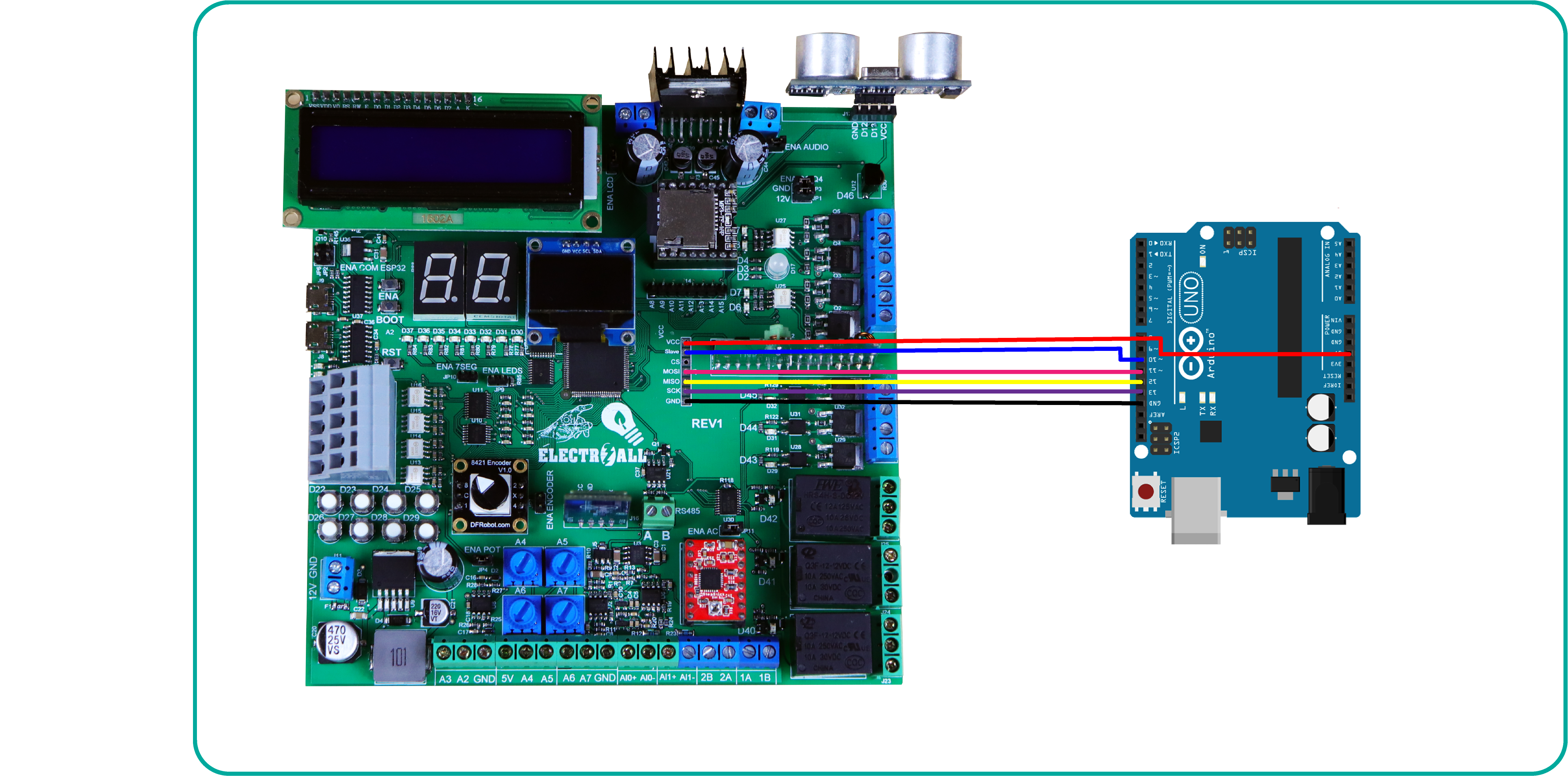
Después de haber subido el gestor de arranque finalmente ya podremos subir cualquier programa como normalmente lo realizamos a través del puerto serie.
//TESTER DIGITAL INPUTS 12VDC

// Digital inputs
const int IN0 = 22;
const int IN1 = 23;
const int IN2 = 24;
const int IN3 = 25;
const int IN4 = 26;
const int IN5 = 27;
const int IN6 = 28;
const int IN7 = 29;

//MOSFET'S OUTPUTS
int LED0 = 30;
int LED1 = 31;
int LED2 = 32;
int LED3 = 33;
int LED4 = 34;
int LED5 = 35;
int LED6 = 36;
int LED7 = 37;

void setup() {

  //DIGITAL INPUTS
  pinMode(IN0, INPUT);
  pinMode(IN1, INPUT);
  pinMode(IN2, INPUT);
  pinMode(IN3, INPUT);
  pinMode(IN4, INPUT);
  pinMode(IN5, INPUT);
  pinMode(IN6, INPUT);
  pinMode(IN7, INPUT);

  //IGBT'S OUTPUTS
  pinMode(LED0, OUTPUT);
  pinMode(LED1, OUTPUT);
  pinMode(LED2, OUTPUT);
  pinMode(LED3, OUTPUT);
  pinMode(LED4, OUTPUT);
  pinMode(LED5, OUTPUT);
  pinMode(LED6, OUTPUT);
  pinMode(LED7, OUTPUT);
}
void loop() {
  if (digitalRead(IN0) == 1)digitalWrite(LED0, 1);
  else digitalWrite(LED0, 0);
  if (digitalRead(IN1) == 1)digitalWrite(LED1, 1);
  else digitalWrite(LED1, 0);
  if (digitalRead(IN2) == 1)digitalWrite(LED2, 1);
  else digitalWrite(LED2, 0);
  if (digitalRead(IN3) == 1)digitalWrite(LED3, 1);
  else digitalWrite(LED3, 0);
  if (digitalRead(IN4) == 1)digitalWrite(LED4, 1);
  else digitalWrite(LED4, 0);
  if (digitalRead(IN5) == 1)digitalWrite(LED5, 1);
  else digitalWrite(LED5, 0);
  if (digitalRead(IN6) == 1)digitalWrite(LED6, 1);
  else digitalWrite(LED6, 0);
  if (digitalRead(IN7) == 1)digitalWrite(LED7, 1);
  else digitalWrite(LED7, 0);

}
int a = 37; ///////////////////////////////////////
int b = 36; ///////////////////////////////////////
int c = 35; ///////////////////////////////////////PINES PARA EL CONTADOR
int d = 34; ///////////////////////////////////////DE UNIDADES
int e = 33; ///////////////////////////////////////
int f = 32; ///////////////////////////////////////
int g = 31; ///////////////////////////////////////
int A = 45;  ///////////////////////////////////////
int B = 44;  ///////////////////////////////////////
int C = 43;  ///////////////////////////////////////
int D = 42;  ///////////////////////////////////////PINES PARA EL CONTADOR
int E = 41;  ///////////////////////////////////////DE DECENAS
int F = 40;  ///////////////////////////////////////
int G = 39;  ///////////////////////////////////////

/////////////////////////////////////////////////////
int dos     [7] = {a, b, c, d, e, f, g}; // UNIDADES
int uno     [7] = {A, B, C, D, E, F, G}; // DECENAS
//--UNIDADES--/////////////////////////////////////////
int unidad0 [7] = {1, 1, 1, 1, 1, 1, 0}; //= #0
int unidad1 [7] = {0, 1, 1, 0, 0, 0, 0}; //= #1
int unidad2 [7] = {1, 1, 0, 1, 1, 0, 1}; //= #2
int unidad3 [7] = {1, 1, 1, 1, 0, 0, 1}; //= #3
int unidad4 [7] = {0, 1, 1, 0, 0, 1, 1}; //= #4
int unidad5 [7] = {1, 0, 1, 1, 0, 1, 1}; //= #5
int unidad6 [7] = {1, 0, 1, 1, 1, 1, 1}; //= #6
int unidad7 [7] = {1, 1, 1, 0, 0, 0, 0}; //= #7
int unidad8 [7] = {1, 1, 1, 1, 1, 1, 1}; //= #8
int unidad9 [7] = {1, 1, 1, 1, 0, 1, 1}; //= #9
//--DECENAS--////////////////////////////////////////////
int decena0 [7] = {1, 1, 1, 1, 1, 1, 0}; //= #0
int decena1 [7] = {0, 1, 1, 0, 0, 0, 0}; //= #1
int decena2 [7] = {1, 1, 0, 1, 1, 0, 1}; //= #2
int decena3 [7] = {1, 1, 1, 1, 0, 0, 1}; //= #3
int decena4 [7] = {0, 1, 1, 0, 0, 1, 1}; //= #4
int decena5 [7] = {1, 0, 1, 1, 0, 1, 1}; //= #5
int decena6 [7] = {1, 0, 1, 1, 1, 1, 1}; //= #6
int decena7 [7] = {1, 1, 1, 0, 0, 0, 0}; //= #7
int decena8 [7] = {1, 1, 1, 1, 1, 1, 1}; //= #8
int decena9 [7] = {1, 1, 1, 1, 0, 1, 1}; //= #9
#include <Keypad.h>
const byte COLUMNAS = 4;
const byte FILAS    = 4;
char teclas [FILAS] [COLUMNAS] = {
  {'1', '2', '3', 'X'},
  {'4', '5', '6', 'B'},
  {'7', '8', '9', 'C'},
  {'*', '0', '#', '='}
};
byte filasPines[FILAS]       = {62, 63, 64, 65}; //Define lineas
byte columnasPines[COLUMNAS] = {66 , 67 , 68 , 69}; //Define columnas
Keypad miTeclado = Keypad( makeKeymap(teclas), filasPines, columnasPines, FILAS, COLUMNAS );

void setup() {
  for (byte i = 0; i < 7; i++) {
    pinMode (uno[i], OUTPUT);
    pinMode (dos[i], OUTPUT);
  }

}

void loop() {

  char tecla = miTeclado.getKey();

  if (tecla == '0' && tecla != NO_KEY) {
    for (byte i = 0; i < 7; i++) {
      digitalWrite (uno[i], unidad0[i]);
    }
  }
  if ((tecla == '1')) {
    for (byte i = 0; i < 7; i++) {
      digitalWrite (uno[i], unidad1[i]);
    }
  }
  if ((tecla == '2')) {
    for (byte i = 0; i < 7; i++) {
      digitalWrite (uno[i], unidad2[i]);
    }
  }
  if ((tecla == '3')) {
    for (byte i = 0; i < 7; i++) {
      digitalWrite (uno[i], unidad3[i]);
    }
  }
  if ((tecla == '4')) {
    for (byte i = 0; i < 7; i++) {
      digitalWrite (uno[i], unidad4[i]);
    }
  }
  if ((tecla == '5')) {
    for (byte i = 0; i < 7; i++) {
      digitalWrite (uno[i], unidad5[i]);
    }
  }
  if ((tecla == '6')) {
    for (byte i = 0; i < 7; i++) {
      digitalWrite (uno[i], unidad6[i]);
    }
  }
  if ((tecla == '7')) {
    for (byte i = 0; i < 7; i++) {
      digitalWrite (uno[i], unidad7[i]);
    }
  }
  if ((tecla == '8')) {
    for (byte i = 0; i < 7; i++) {
      digitalWrite (uno[i], unidad8[i]);
    }
  }
  if ((tecla == '9')) {
    for (byte i = 0; i < 7; i++) {
      digitalWrite (uno[i], unidad9[i]);
    }
  }

}
// SET IQ1Q0T OTPUTS
const int Q0 = 6;
const int Q1 = 7;
const int Q2 = 8;
const int Q3 = 9;
/////////////////////////
//****POTENTIOMETEQ2 A4-A7***
void setup() {
pinMode(Q0,OUTPUT);
pinMode(Q1,OUTPUT);
pinMode(Q2,OUTPUT);
pinMode(Q3,OUTPUT);
}
void loop() {
int VQ0= map(analogRead(A4),0,1023,0,255);
analogWrite(Q0,VQ0);

int VQ1= map(analogRead(A5),0,1023,0,255);
analogWrite(Q1,VQ1);

int VQ2= map(analogRead(A6),0,1023,0,255);
analogWrite(Q2,VQ2);

int VQ3= map(analogRead(A7),0,1023,0,255);
analogWrite(Q3,VQ3);
}
// SET IQ1Q0T OTPUTS
const int B = 2;
const int G = 3;

/////////////////////////
//****INPUT (0-10V) A2-A3***
void setup() {
  Serial.begin(9600);
  pinMode(B, OUTPUT);
  pinMode(G, OUTPUT);

}
void loop() {
  int VQ0 = map(analogRead(A3), 0, 1023, 0, 255);
  analogWrite(B, VQ0);
  Serial.println(analogRead(A3));

  int VQ1 = map(analogRead(A2), 0, 1023, 0, 255);
  analogWrite(G, VQ1);
  Serial.println(analogRead(A2));
  delay(1000);

}
const int B = 2;

void setup() {
  Serial.begin(9600);
  //LED BLUE OUPUTS
  pinMode (B, OUTPUT);

}

void loop() {
  //CURRENT INPUT (4-20mA) A0-A1 "4mA = 0V; 20mA = 2.7V
  // VOLTAGE VALUE
  int analog0 = analogRead(A1);
  float voltage0 = analog0 * 0.004887585532746823069403714565;// = 5V/1023
  Serial.print("voltage0 = " );
  Serial.print (voltage0);
  Serial.println ("V");
  int pwm_out = voltage0 * 94.44444444444444; // = 255/2.70V
  analogWrite(B, pwm_out);
  delay(700);// Opcional
}
// SET T= TRIACS  RL= RELAYS
const int T0 = 45;
const int T1 = 44;
const int T2 = 43;
const int RL0 = 42;
const int RL1 = 41;
const int RL2 = 40;

const int IN0 = 22;
const int IN1 = 23;
const int IN2 = 24;
const int IN3 = 25;
const int IN4 = 26;
const int IN5 = 27;
/////////////////////////

void setup() {

  pinMode(IN0, INPUT);
  pinMode(IN1, INPUT);
  pinMode(IN2, INPUT);
  pinMode(IN3, INPUT);
  pinMode(IN4, INPUT);
  pinMode(IN5, INPUT);

  pinMode(T0, OUTPUT);
  pinMode(T1, OUTPUT);
  pinMode(T2, OUTPUT);
  pinMode(RL0, OUTPUT);
  pinMode(RL1, OUTPUT);
  pinMode(RL2, OUTPUT);
}
void loop() {
  if (digitalRead(IN0) == 1)digitalWrite(T0, 1);
  else digitalWrite(T0, 0);
  if (digitalRead(IN1) == 1)digitalWrite(T1, 1);
  else digitalWrite(T1, 0);
  if (digitalRead(IN2) == 1)digitalWrite(T2, 1);
  else digitalWrite(T2, 0);
  if (digitalRead(IN3) == 1)digitalWrite(RL0, 1);
  else digitalWrite(RL0, 0);
  if (digitalRead(IN4) == 1)digitalWrite(RL1, 1);
  else digitalWrite(RL1, 0);
  if (digitalRead(IN5) == 1)digitalWrite(RL2, 1);
  else digitalWrite(RL2, 0);
}
#include <LiquidCrystal_I2C.h> // Debe descargar la Libreria que controla el I2C
#include<Wire.h>

LiquidCrystal_I2C lcd(0x27, 16, 2);
int trigger = 13;           // declaramos la palabra trigger como un tipo entero y al mismo tiempo reemplaza al pin 9
int echo = 12;           // declaramos la palabra echo como un tipo entero y al mismo tiempo reemplaza al pin 8
float tiempo_de_espera, distancia; // creamos una variable de fotante; es decir, nos puede dar resultados en decimales.

void setup() {
  pinMode (trigger, OUTPUT); // declarmos el pin 9 como salida
  pinMode (echo, INPUT);   // declaramos el 8 como entrada
  lcd.init();
  lcd.backlight();
  lcd.clear();
  lcd.setCursor(0, 0);
  lcd.print("ELECTROALL"); // Mensaje a despegar
  delay(3000);
  lcd.clear();

}

void loop() {

  digitalWrite (trigger, LOW); // ponemos en bajo el pin 8 durante 2 microsegundos
  delayMicroseconds(2);
  digitalWrite (trigger, HIGH);// ahora ponemos en alto pin 8 durante 10 microsegundos;
  delayMicroseconds (10);     // pues este el momento en que emite el sonido durante 10 segungos
  digitalWrite (trigger, LOW); // ahora ponemos en bajo pin 8

  tiempo_de_espera = pulseIn (echo, HIGH); // pulseIn, recoge la señal del sonido que emite el trigger

  /*La función pulseIn espera la aparición de un pulso en una entrada y mide su duración, dando como resultado la duración medida
    El primer parámetro (ECHO) es el pin sobre el que se realizará la medición.
    Y el segundo parámetro (HIGH) indica si el pulso a esperar será un 1 (HIGH) o un 0 (LOW).
  */
  distancia = (tiempo_de_espera / 2) / 29.15; // formula para hallar la distancia

  lcd.setCursor(0, 0);
  lcd.print("distancia"); // Mensaje a despegar
  lcd.setCursor(0, 1);
  lcd.print(distancia); // Mensaje a despegar
   lcd.setCursor(7, 1);
  lcd.print("cm");
  delay(3000);
  lcd.clear();
}
#include "Arduino.h"
#include "SoftwareSerial.h"
#include "DFRobotDFPlayerMini.h"

//Pulsadores
const int s1 = 22; // pulsadores
const int s2 = 23;

const int led = 30; // led

int state1 = 0; // estados para las entradas digitales
int last1 = 1;
int state2 = 0;
int last2 = 1;

SoftwareSerial mySoftwareSerial(10, 11); // RX, TX
DFRobotDFPlayerMini myDFPlayer;
void printDetail(uint8_t type, int value);

void setup()
{
  mySoftwareSerial.begin(9600);
  Serial.begin(115200);

  Serial.println();
  Serial.println(F("DFRobot DFPlayer Mini Demo"));
  Serial.println(F("Initializing DFPlayer ... (May take 3~5 seconds)"));

  if (!myDFPlayer.begin(mySoftwareSerial)) {  //Use softwareSerial to communicate with mp3.
    Serial.println(F("Unable to begin:"));
    Serial.println(F("1.Please recheck the connection!"));
    Serial.println(F("2.Please insert the SD card!"));
    while (true);
  }
  Serial.println(F("DFPlayer Mini online."));

  myDFPlayer.setTimeOut(500); //Set serial communictaion time out 500ms

  //----Set volume----
  myDFPlayer.volume(20);  //Set volume value (0~30).
  myDFPlayer.volumeUp(); //Volume Up
  myDFPlayer.volumeDown(); //Volume Down

  //----Set different EQ----
  myDFPlayer.EQ(DFPLAYER_EQ_NORMAL);

  //----Set device we use SD as default----
  myDFPlayer.outputDevice(DFPLAYER_DEVICE_SD);

  pinMode(s1, INPUT);
  pinMode(s2, INPUT);

  pinMode(led, OUTPUT);

}

void loop()
{
  state1 = digitalRead(s1);
  state2 = digitalRead(s2);
  int vol = map(analogRead(A4),0,1023, 0, 30);
 myDFPlayer.volume(vol);  //Set volume value (0~30).

  if (state1 != last1) {
    if (state1 == LOW) {
      myDFPlayer.next();
      Serial.print(state1);
      digitalWrite(led, 1);
      delay(1000);
    }
  }
  last1  = state1;

  if (state2 != last2 ) {
    if (state2 == LOW) {
      myDFPlayer.previous();
      digitalWrite(led, 0);
      delay(1000);
    }
  }
  last2  = state2;

}
int pasos = 47;  // usamos el  pin 6 para generar pulsos (pasos)
int direc = 48;  // usamos el  pin 7 para la direccion (sentido horario, antihorario)
//int tiempo=1;   // tiempo que dura para girar una vuelta entera
void setup() {
 pinMode (pasos, OUTPUT);
 pinMode (direc, OUTPUT);
}

void loop() {
int c_pasos;
for (c_pasos =0; c_pasos <=2000;c_pasos ++){
 digitalWrite (direc,HIGH);
 digitalWrite (pasos,true);
 delayMicroseconds (1000);
 digitalWrite (pasos,false);
  delayMicroseconds (1000);
}
for (c_pasos =2000; c_pasos >=0;c_pasos --){
 digitalWrite (direc,LOW);
 digitalWrite (pasos,true);
 delayMicroseconds (1000);
 digitalWrite (pasos,false);
  delayMicroseconds (1000);
}

}
//APAGADO Y PRENDIDO DE LED BT.
//CARLONCHITOTONIC.
int led=4; //declaramos un valor entero, para luego trabajar con (led) en el resto de la estructura
int estado=0; // =de arriba

void setup(){
  Serial.begin(9600); //establecemos la comunicacion serial bluetooth.
  pinMode(led,OUTPUT); //declaramos el pin 13 como salida
}

void loop(){
 if(Serial.available()>0)// nos aseguramos que el puerto serial este habilitado.
 {
 estado = Serial.read(); // almacenamos los doatos
 }
 switch (estado){
case'A':  digitalWrite(led,HIGH);
break;
 case'B':  digitalWrite(led,LOW);
break;
 }

}
/*
                CREADO POR      :{==[=======>>>> ELECTROALL <<<<<=======]==}
                INSTAGRAM       : https://www.instagram.com/electroall_/
                                  ó  @electroall_
                FACEBOOK        : https://web.facebook.com/ELECTROALL.ELECTRONICA/?_rdc=1&_rdr
                PÁGINA WEB      : https://www.electroallweb.com/
                YOUTUBE         : https://www.youtube.com/c/ELECTROALL
           ________________________________________________________
            {==[=======> (Testing CLOCK REAL TIME ) <=======]==}
           ________________________________________________________
*/
#include <Wire.h>
#include "Sodaq_DS3231.h"
#include <LiquidCrystal_I2C.h> // Debe descargar la Libreria que controla el I2C
LiquidCrystal_I2C lcd(0x27, 16, 2);
char DiaSemana[][4] = {"Dom", "Lun", "Mar", "Mie", "Jue", "Vie", "Sab" };
const int Q1 = 13 ; // salida alarma
// La linea fija la fecha, hora y dia de la semana, se debe suprimir la linea en la segunda carga
// Ejemplo 2017 diciembre 06, 22:00:00  dia 1-Lunes (0=Dom, 1=Lun, 2=Mar, 3=Mie, 4=Jue, 5=Vie, 6=Sab)
//DateTime dt(2020, 11, 20, 21, 36, 00, 1);

const int E_OT = 63; // habilitador de pines de salida reles,
void setup ()
{

  Serial.begin(9600);
  Wire.begin();
  rtc.begin();
  lcd.init();
  lcd.backlight();
  lcd.clear();
  // La linea fija la fecha, hora y dia de la semana, se debe suprimir la linea en la segunda carga
  // rtc.setDateTime(dt);
  pinMode(E_OT, OUTPUT);
  digitalWrite(E_OT, 1);// Con bajo se habilita. Con alto se desabilita
  pinMode(Q1, OUTPUT);
}
void loop ()
{
  DateTime now = rtc.now();
  Serial.print(now.year(), DEC);
  Serial.print('/');
  Serial.print(now.month(), DEC);
  Serial.print('/');
  Serial.print(now.date(), DEC);
  Serial.print(' ');
  Serial.print(now.hour(), DEC);
  Serial.print(':');
  Serial.print(now.minute(), DEC);
  Serial.print(':');
  Serial.print(now.second(), DEC);
  Serial.print(' ');
  Serial.print(DiaSemana[now.dayOfWeek()]);
  Serial.println();
  lcd.setCursor(0, 0);
  lcd.print(now.year(), DEC);
  lcd.print('/');
  lcd.print(now.month(), DEC);
  lcd.print('/');
  lcd.print(now.date(), DEC);
  lcd.setCursor(0, 1);
  lcd.print(now.hour(), DEC);
  lcd.print(':');
  lcd.print(now.minute(), DEC);
  lcd.print(':');
  lcd.print(now.second(), DEC);
  lcd.print(' ');
  lcd.print(DiaSemana[now.dayOfWeek()]);
  //delay(1000); // Se actualiza cada segundo
  //lcd.clear();

  if ((now.dayOfWeek()) == 1 && now.hour() == 21 && now.minute() == 55 && now.second() <= 30) { // MONDAY
    digitalWrite(Q1, 1);
  }
  else {
    digitalWrite(Q1, 0);
  }
}
#include <Modbusino.h>
ModbusinoSlave modbusino_slave(1);
/* Allocate a mapping of 10 values */
uint16_t tab_reg[10];
int i;
int sensorPin = A2;
int sensorValue = 0;
void setup() {
    modbusino_slave.setup(115200);
    pinMode(relay, OUTPUT);
}
void loop() {
  sensorValue = analogRead(sensorPin);
tab_reg[4] = sensorValue;
    modbusino_slave.loop(tab_reg, 10);
      i = i++;
}
/*
                CREADO POR      :{==[=======>>>> ELECTROALL <<<<<=======]==}
                INSTAGRAM       : https://www.instagram.com/carlos_j_fuentess/
                                  ó  @carlos_j_fuentess
                FACEBOOK        : https://web.facebook.com/ELECTROALL.ELECTRONICA/?_rdc=1&_rdr
                PÁGINA WEB      : https://www.electroallweb.com/
                YOUTUBE         : https://www.youtube.com/c/ELECTROALL
           ________________________________________________________
     {==[=======> (CONTADOR ) <=======]==}
           ________________________________________________________
*/

// no cambiar las el const int
const int  pulsador_asc = 23;    // ENTRADA IN1 PARA CONTAR ASCENDENTEMENTE
// ascendentes
const int  pulsador_des = 22;    // ENTRADA IN2 PARA CONTAR DESCENDENTEMENTE
// descendentes

//VARIABLES PARA EL CONTADOR ASCENDIENTE
// estas variables si puede ser cambiado
int contador            = 0;   // contador para el numero de veces presinados
int estado_pulsador_asc = 0;         // estado actual del pulsador
int lastButtonState_asc = 0;     // estado anterior del pulsador

//VARIABLES PARA EL CONTADOR DESCENDIENTE
// estas variables si puede ser cambiado

int estado_pulsador_des = 0;         // estado actual del pulsador
int lastButtonState_des = 0;     // estado anterior del pulsador

const int sir = 4;
//////////////////////////////////////////////////
int a = 37; ///////////////////////////////////////
int b = 36; ///////////////////////////////////////
int c = 35; ///////////////////////////////////////PINES PARA EL CONTADOR
int d = 34; ///////////////////////////////////////DE UNIDADES
int e = 33; ///////////////////////////////////////
int f = 32; ///////////////////////////////////////
int g = 31; ///////////////////////////////////////
int A = 45;  ///////////////////////////////////////
int B = 44;  ///////////////////////////////////////
int C = 43;  ///////////////////////////////////////
int D = 42;  ///////////////////////////////////////PINES PARA EL CONTADOR
int E = 41;  ///////////////////////////////////////DE DECENAS
int F = 40;  ///////////////////////////////////////
int G = 39;  ///////////////////////////////////////

/////////////////////////////////////////////////////
int dos    [7] = {a, b, c, d, e, f, g}; // UNIDADES
int uno     [7] = {A, B, C, D, E, F, G}; // DECENAS
//--UNIDADES--/////////////////////////////////////////
int unidad0 [7] = {1, 1, 1, 1, 1, 1, 0}; //= #0
int unidad1 [7] = {0, 1, 1, 0, 0, 0, 0}; //= #1
int unidad2 [7] = {1, 1, 0, 1, 1, 0, 1}; //= #2
int unidad3 [7] = {1, 1, 1, 1, 0, 0, 1}; //= #3
int unidad4 [7] = {0, 1, 1, 0, 0, 1, 1}; //= #4
int unidad5 [7] = {1, 0, 1, 1, 0, 1, 1}; //= #5
int unidad6 [7] = {1, 0, 1, 1, 1, 1, 1}; //= #6
int unidad7 [7] = {1, 1, 1, 0, 0, 0, 0}; //= #7
int unidad8 [7] = {1, 1, 1, 1, 1, 1, 1}; //= #8
int unidad9 [7] = {1, 1, 1, 1, 0, 1, 1}; //= #9
//--DECENAS--////////////////////////////////////////////
int decena0 [7] = {1, 1, 1, 1, 1, 1, 0}; //= #0
int decena1 [7] = {0, 1, 1, 0, 0, 0, 0}; //= #1
int decena2 [7] = {1, 1, 0, 1, 1, 0, 1}; //= #2
int decena3 [7] = {1, 1, 1, 1, 0, 0, 1}; //= #3
int decena4 [7] = {0, 1, 1, 0, 0, 1, 1}; //= #4
int decena5 [7] = {1, 0, 1, 1, 0, 1, 1}; //= #5
int decena6 [7] = {1, 0, 1, 1, 1, 1, 1}; //= #6
int decena7 [7] = {1, 1, 1, 0, 0, 0, 0}; //= #7
int decena8 [7] = {1, 1, 1, 1, 1, 1, 1}; //= #8
int decena9 [7] = {1, 1, 1, 1, 0, 1, 1}; //= #9
int counter = 0; //CONTADOR UNIDADES
int contadorD = 0; //CONTADOR DECENAS
int counter1 = 0; // CONTADOR PARA EL CAMBIO DE COLOR

void setup() {
  Serial.begin(9600);

  pinMode(pulsador_asc, INPUT); //Resistencia de pullup interna
  pinMode(pulsador_des, INPUT); //Resistencia de pullup interna
  pinMode(sir, OUTPUT);

  for (byte i = 0; i < 7; i++) {
    pinMode (uno[i], OUTPUT);
    pinMode (dos[i], OUTPUT);
  }
}

void loop() {
  //  almacenamos la lectura de la entrada de pin 2
  estado_pulsador_asc = digitalRead(pulsador_asc);
  estado_pulsador_des = digitalRead(pulsador_des);

  // comparar el estado del botón a su estado anterior
  if (estado_pulsador_asc != lastButtonState_asc) {
    // si el estado fue cambiado, incremente el conteo
    if (estado_pulsador_asc == LOW) {
      // si el estado actual es alto, entonces
      // que pase de off a on:
      if (counter < 99) {
        contador++;
        counter++;
        Serial.print("CONTEO= ");
        Serial.println(contador);
        Serial.print("CONTEO_sis= ");
        Serial.println(counter);
        delay(100);
        if (counter == 10 || counter == 20 || counter == 30 || counter == 40 || counter == 50 || counter == 60 || counter == 70 || counter == 80 || counter == 90) {
          contadorD++;
          delay(100);
        }
      }
    }
  }
  lastButtonState_asc  = estado_pulsador_asc;
  // comparar el estado del botón a su estado anterior
  if (estado_pulsador_des != lastButtonState_des ) {
    // si el estado fue cambiado, decrementa el conteo
    if (estado_pulsador_des == HIGH) {
      // si el estado actual es alto, entonces
      // que pase de off a on:
      if (counter > 0 ) {
        contador--;
        counter--;
        Serial.print("CONTEO= ");
        Serial.println(contador);
        Serial.print("CONTEO_sis= ");
        Serial.println(counter);
        delay(100);
        if (counter == 9 || counter == 19 || counter == 29 || counter == 39 || counter == 49 || counter == 59 || counter == 69 || counter == 79 || counter == 89) {
          contadorD--;
          delay(100);
        }
        if (contador == -1) {
          contador = 9;
        }
      }
    }
  }
  //guarda el último estado actual como el ultimo estado
  //para el proximo bucle
  lastButtonState_des  = estado_pulsador_des;
  if (contador == 10) {
    contador = 0;

  }

  switch (contador) {
    case 0:
      for (byte i = 0; i < 7; i++) {
        digitalWrite (uno[i], unidad0[i]);
      }
      break;
    case 1:
      for (byte i = 0; i < 7; i++) {
        digitalWrite (uno[i], unidad1[i]);
      }
      break;
    case 2:
      for (byte i = 0; i < 7; i++) {
        digitalWrite (uno[i], unidad2[i]);
      }
      break;
    case 3:
      for (byte i = 0; i < 7; i++) {
        digitalWrite (uno[i], unidad3[i]);
      }
      break;
    case 4:
      for (byte i = 0; i < 7; i++) {
        digitalWrite (uno[i], unidad4[i]);
      }
      break;
    case 5:
      for (byte i = 0; i < 7; i++) {
        digitalWrite (uno[i], unidad5[i]);
      }
      break;
    case 6:
      for (byte i = 0; i < 7; i++) {
        digitalWrite (uno[i], unidad6[i]);
      }
      break;
    case 7:
      for (byte i = 0; i < 7; i++) {
        digitalWrite (uno[i], unidad7[i]);
      }
      break;
    case 8:
      for (byte i = 0; i < 7; i++) {
        digitalWrite (uno[i], unidad8[i]);
      }
      break;
    case 9:
      for (byte i = 0; i < 7; i++) {
        digitalWrite (uno[i], unidad9[i]);
      }
      break;
  }
  switch (contadorD) {
    case 0:
      for (byte i = 0; i < 7; i++) {
        digitalWrite (dos[i], decena0[i]);
      }
      break;
    case 1:
      for (byte i = 0; i < 7; i++) {
        digitalWrite (dos[i], decena1[i]);
      }
      break;
    case 2:
      for (byte i = 0; i < 7; i++) {
        digitalWrite (dos[i], decena2[i]);
      }
      break;
    case 3:
      for (byte i = 0; i < 7; i++) {
        digitalWrite (dos[i], decena3[i]);
      }
      break;
    case 4:
      for (byte i = 0; i < 7; i++) {
        digitalWrite (dos[i], decena4[i]);
      }
      break;
    case 5:
      for (byte i = 0; i < 7; i++) {
        digitalWrite (dos[i], decena5[i]);
      }
      break;
    case 6:
      for (byte i = 0; i < 7; i++) {
        digitalWrite (dos[i], decena6[i]);
      }
      break;
    case 7:
      for (byte i = 0; i < 7; i++) {
        digitalWrite (dos[i], decena7[i]);
      }
      break;
    case 8:
      for (byte i = 0; i < 7; i++) {
        digitalWrite (dos[i], decena8[i]);
      }
      break;
    case 9:
      for (byte i = 0; i < 7; i++) {
        digitalWrite (dos[i], decena9[i]);
      }
      break;

  }
  if (counter >= 50) {
    digitalWrite(sir, 1);
  }
  else {
    digitalWrite(sir, 0);
  }

}