INTRODUCCIÓN
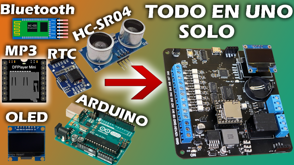
Hace semanas atrás se publicó un video de una tarjeta entrenadora que contenía distintos tipos de módulos; como LA PANTALLA OLED, EL RTC, LA PANTALLA LCD, etc. Para esta versión agregaremos un Modulo Bluetooth, un sensor ultrasonido, un reproductor mp3 y 8 entradas digitales.
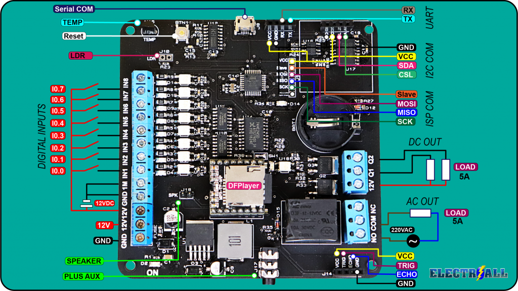
Básicamente este board entrenadora de módulos contiene las siguientes características y dispositivos. un arduino nano, Un sensor ultrasonido, un módulo de tiempo real, una pantalla OLED, un módulo bluetooth(hc-06), un reproductor mp3 con salida a un amplificador, un sensor de temperatura, un sensor de LDR, 8 entradas digitales de 5-12V, una salida a relé y dos salidas a transistores.
Con todos estos dispositivos integrados en una sola tarjeta prácticamente se estaría ganando el tiempo, porque ya no necesitamos realizar ninguna conexión adicional a ningún módulo.
ESPECIFICACIONES TÉCNICAS

- Tensión de alimentación……………………….…………12VDC
- Corriente de alimentación………………….……………140mA
- Programación Directa………………………………….….Ordenador – Tarjeta entrenadora
- Entorno de programación………………………..……..Arduino IDE
- Reloj de Tiempo Real…………………………………………..SÍ
- Reproductor mp3……………………………………………………….Sí
- OLED………………………………………………………………………SÍ
- Sensor ultrasonico………………………………………………………..Sí
- bluetooth.……………………………………………………………..SÍ
- ISP com………………………………………………………………….SÍ
- Sensor de temperatura incorporada……………….……..SÍ
- Sensor LDR……………………………………………………………………Sí
- Entradas digitales externo(5-12V)…………………………..8
- Salida RELAY………………………………………………1
- Tensión salida AC…………………………..….……220V
- Corriente AC………………………………………….10A
- Tensión DC……………………………………………30V
- Corriente DC…………………………………………10A
- Salida TRANSISTOR IGBT…..………………………….1
- Tensión salida DC…………………………….……12V
- Corriente DC……………………….……………….1A
- Salida TRANSISTOR BJT…..…..……………………….1
- Tensión salida DC…………………………….……12V
- Corriente DC……………………….……………….1A
- Condiciones ambientales min………………………….-10°
- Condiciones ambientales max…………………..…….55°
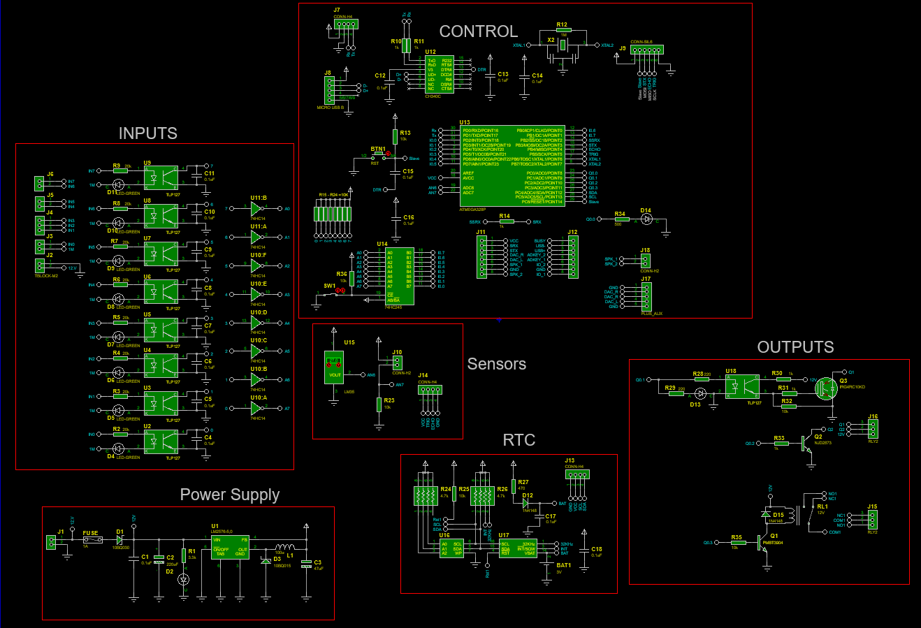
LISTA DE COMPONENTES ELECTRÓNICOS
- U1; Regulador Step-Down LM2576S-5.0/TR (see & buy)
- U2, U8, U18; Optoacoplador TLP127 (see & buy)
- U9; Optoacoplador MOC3041 (see & buy)
- U10-U11; Circuito integrado 74HC14D (see & buy)
- U12; Circuito Integrado Transceiver USB CH340C ( see & buy )
- U13; Microcontrolador ATmega328p AU (see & buy)
- U14;Circuito integrado 74HC245D (see & buy)
- U15; Sensor de temperatura LM35 (see & buy)
- U16; I2C Serial EEPROM ( see & buy )
- U17; Maxin Integrated RTC DS3231SN ( see & buy )
- J8; Micro USB tipo B (see & buy)
- J7,J9,J13,J14,J18; Pines espadines Macho (see & buy)
- J11,J12; DFPlayer (see & buy)
- J17; Plug-in headphone holder 5 Female Horizontal(see & buy)
- J4, J15,J16; borneras 3PIN (see & buy)
- J1,J2,J3,J5,J6; Borneras 2PIN (see & buy)
- BAT1; Sócalo para batería (see & buy)
- D1; Diodo Schottky SS14-T (see & buy)
- D2,D4-D11,D13; Led smd 1206 ( see & buy )
- D12,D15; Diodo rectificador SOD-123 (see & buy)
- D3; Diodo Schottky Barrier Diodes B330A-13-F (see & buy)
- C1; Capacitor ceramico 0.1uF(1206) (see & buy)
- C2; Capacitor electrolítico SMD 220uF ( see & buy )
- C3; Capacitor electrolítico SMD 47uF ( see & buy )
- C4-C18; Capacitor cerámico 0.1uF (0603) ( see & buy )
- Q1; Transistor SOT23 PNP ( see & buy )
- Q3; Transistor IGBT ( see & buy )
- Q2; Transistor DPAK NPN (see & buy)
- R1; Resistencia SMD 1/10W, 3.3k Ohm, package 0603 ( see & buy )
- R2-R9; Resistencia SMD 1/4W, 10k Ohm, package 1206 ( see & buy )
- R12; Resistencia SMD 1/10W, 1M Ohm, package 0603 ( see & buy )
- R28-R29; Resistencia SMD 1/10W, 470 Ohm, package 0603 ( see & buy )
- R10,R11,R14,R34,R35; Resistencia SMD 1/10W, 1k Ohm, package 0603 ( see & buy )
- R13,R15-R23,R25,R36-R23, R31-R34; Resistencia SMD 1/10W, 10k Ohm, package 0603 ( see & buy )
- R27; Resistencia SMD 1/8W, 470 Ohm, package 0805 ( see & buy )
- R24, R26; Resistencia SMD 1/10W, array 4pack 4.7k Ohm, package 0603 ( see & buy )
- R30,R31; Resistencia SMD 1/8W, 1k Ohm, package 0805 ( see & buy )
- R32; Resistencia SMD 1/8W, 10k Ohm, package 0805 ( see & buy )
- RL1; Relay 12V (see & buy)
- L1; Inductor 100uH (see & buy)
- BTN1; Pulsador SMD (see & buy)
- X1; Crystal SMD 16Mhz ( see & buy )
PASOS PARA SUBIR UN PROGRAMA
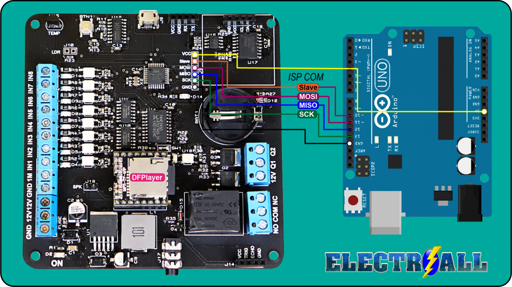
PASO 1 : SUBIR GESTOR DE ARRANQUE (BOOTLOADER)
Para poder usar un microcontrolador nuevo (atmega328p-pu), es necesario subir un un gestor de arranque como también llamado “BOOTLOADER”, esto nos facilitará subir programas en futuras ocasiones.
finalmente para quemar el bootloader se tendrá que realizar a través de los pines ISP, que prácticamente serían los pines [ (MOSI=11) (MISO = PIN12) (SCK=PIN13) (Slave=PIN10) ]. Para subir y quemar el gestor de arranque necesitaremos un arduino UNO ó MEGA y realizar las siguientes conexiones (ARDUINO UNO – MAIN BOARD).
PASO 2 : SUBIR PROGRAMA; PC – MAIN BOARD
Después de haber subido el gestor de arranque finalmente ya podremos subir cualquier programa como normalmente lo realizamos a través del puerto serie.
PARTES Y CONEXIONES EXTERNAS
CÓDIGOS DE PRUEBA
ENTRADAS Y DFPLAYER
#include "Arduino.h"
#include "SoftwareSerial.h"
#include "DFRobotDFPlayerMini.h"

//Pulsadores
const int s1 = 2;
const int s2 = 3;
const int s3 = 4;
const int s4 = 5;
const int s5 = 6;
const int s6 = 7;
const int s7 = 8;
const int s8 = 9;

int state1 = 0;
int last1 = 1;
int state2 = 0;
int last2 = 1;
int state3 = 0;
int last3 = 1;
int state4 = 0;
int last4 = 1;
int state5 = 0;
int last5 = 1;
int state6 = 0;
int last6 = 1;
int state7 = 0;
int last7 = 1;
int state8 = 0;
int last8 = 1;

SoftwareSerial mySoftwareSerial(11, 10); // RX, TX
DFRobotDFPlayerMini myDFPlayer;
void printDetail(uint8_t type, int value);

void setup()
{
  mySoftwareSerial.begin(9600);
  Serial.begin(115200);

  Serial.println();
  Serial.println(F("DFRobot DFPlayer Mini Demo"));
  Serial.println(F("Initializing DFPlayer ... (May take 3~5 seconds)"));

  if (!myDFPlayer.begin(mySoftwareSerial)) {  //Use softwareSerial to communicate with mp3.
    Serial.println(F("Unable to begin:"));
    Serial.println(F("1.Please recheck the connection!"));
    Serial.println(F("2.Please insert the SD card!"));
    while (true);
  }
  Serial.println(F("DFPlayer Mini online."));

  myDFPlayer.setTimeOut(500); //Set serial communictaion time out 500ms

  //----Set volume----
  myDFPlayer.volume(25);  //Set volume value (0~30).
  myDFPlayer.volumeUp(); //Volume Up
  myDFPlayer.volumeDown(); //Volume Down

  //----Set different EQ----
  myDFPlayer.EQ(DFPLAYER_EQ_NORMAL);

  //----Set device we use SD as default----
  myDFPlayer.outputDevice(DFPLAYER_DEVICE_SD);

  pinMode(s1, INPUT);
  pinMode(s2, INPUT);
  pinMode(s3, INPUT);
  pinMode(s4, INPUT);
  pinMode(s5, INPUT);
  pinMode(s6, INPUT);
  pinMode(s7, INPUT);
  pinMode(s8, INPUT);

}

void loop()
{
  state1 = digitalRead(s1);
  state2 = digitalRead(s2);
  state3 = digitalRead(s3);
  state4 = digitalRead(s4);
  state5 = digitalRead(s5);
  state6 = digitalRead(s6);
  state7 = digitalRead(s7);
  state8 = digitalRead(s8);

  if (state1 != last1) {
    if (state1 == HIGH) {
      myDFPlayer.play(1);
      Serial.print(state1);
      delay(1000);
    }
  }
  last1  = state1;

  if (state2 != last2 ) {
    if (state2 == HIGH) {
      myDFPlayer.play(2);
      Serial.print(state2);
      delay(1000);
    }
  }
  last2  = state2;

  if (state3 != last3 ) {
    if (state3 == HIGH) {
      myDFPlayer.play(3);
      Serial.print(state3);
      delay(1000);
    }
  }
  last3  = state3;

  if (state4 != last4 ) {
    if (state4 == HIGH) {
      myDFPlayer.play(4);
      Serial.print(state4);
    }
    delay(1000);
  }

last4  = state4;

if (state5 != last5 ) {
  if (state5 == HIGH) {
    myDFPlayer.play(5);
    Serial.print(state5);
    delay(1000);
  }
}
last5  = state5;

if (state6 != last6 ) {
  if (state6 == HIGH) {
    myDFPlayer.play(6);
    Serial.print(state6);
    delay(1000);
  }
}
last6  = state6;

if (state7 != last7 ) {

  if (state7 == HIGH) {
    myDFPlayer.play(7);
    Serial.print(state7);
    delay(1000);
  }
}
last7  = state7;

if (state8 != last8 ) {
  if (state8 == HIGH) {
    myDFPlayer.play(8);
    Serial.print(state8);
    delay(1000);
  }
}
last8  = state8;

}
OLED
   //////////////////////////////////////////////////////////////
  //      Creditos colega YT:https://www.youtube.com/watch?v=qWP3fMyZ158 //
 ////////////////////////////////////////////////////////////////
#include "U8glib.h" // Incluir la libreria u8g para usar la pantalla OLED 0.96
///////////////////////////Declaracion de variables /////////////////////////////////////////
int tempC=0;
int reading;
int tempPin = A6;
//////////////////////////////////////////////////////////////////////////////////////

U8GLIB_SSD1306_128X64 u8g(U8G_I2C_OPT_NO_ACK);//Especifica el nombre de la pantalla que nosotros tenemos

/////////////////////////////////////////////////////////////////////////////////

///////////Codigo en Hex (exagesimal que mapea la imagen en la pantalla/////////////////////////
static unsigned char temp[] U8G_PROGMEM = {
  0x00, 0x00, 0x00, 0x00, 0x00, 0x00, 0x00, 0x00, 0x00, 0x00, 0x00, 0x00, 0x00, 0x00, 0x00, 0x00,
0x00, 0x00, 0x00, 0x03, 0x00, 0x70, 0x00, 0x00, 0x00, 0x00, 0x00, 0x03, 0x81, 0xFC, 0x00, 0x00,
0x00, 0x00, 0x00, 0x07, 0xC3, 0x06, 0x00, 0x00, 0x00, 0x00, 0x00, 0x07, 0xC6, 0x03, 0x00, 0x00,
0x00, 0x00, 0x00, 0x0F, 0xC4, 0x01, 0x00, 0x00, 0x00, 0x00, 0x00, 0x07, 0xC4, 0x01, 0x00, 0x00,
0x00, 0x00, 0x00, 0x01, 0x0C, 0x01, 0x80, 0x00, 0x00, 0x00, 0x00, 0x00, 0x0C, 0x01, 0x80, 0x00,
0x00, 0x30, 0x00, 0x00, 0x0C, 0x01, 0x83, 0xFF, 0x00, 0x3E, 0x00, 0x00, 0x0C, 0x01, 0x80, 0x00,
0x00, 0x3F, 0x00, 0x00, 0x0C, 0x01, 0x80, 0x00, 0x00, 0x3F, 0x00, 0x3F, 0xFC, 0x71, 0x80, 0x00,
0x00, 0x3E, 0x00, 0xF8, 0x7C, 0x71, 0x80, 0x00, 0x00, 0x1E, 0x03, 0x80, 0x0C, 0x71, 0x83, 0xE0,
0x00, 0x08, 0x0E, 0x00, 0x0C, 0x71, 0x83, 0xE0, 0x00, 0x00, 0x18, 0x00, 0x0C, 0x71, 0x80, 0x00,
0x00, 0x00, 0x30, 0x00, 0x0C, 0x71, 0x80, 0x00, 0x00, 0x00, 0x60, 0x00, 0x0C, 0x71, 0x80, 0x00,
0x00, 0x00, 0xC0, 0x00, 0x0C, 0x71, 0x80, 0x00, 0x00, 0x01, 0x80, 0x00, 0x0C, 0x71, 0x83, 0xFF,
0x00, 0x01, 0x00, 0x00, 0x0C, 0x71, 0x83, 0xFF, 0x00, 0x03, 0x00, 0x00, 0x0C, 0x71, 0x80, 0x00,
0x00, 0x02, 0x00, 0x00, 0x0C, 0x71, 0x80, 0x00, 0x00, 0x06, 0x00, 0x00, 0x0C, 0x71, 0x80, 0x00,
0x00, 0x06, 0x00, 0x00, 0x0C, 0x71, 0x80, 0x00, 0x00, 0x04, 0x00, 0x00, 0x0C, 0x71, 0x83, 0xE0,
0x00, 0x0C, 0x00, 0x00, 0x0C, 0x71, 0x80, 0x00, 0x06, 0x0C, 0x00, 0x00, 0x0C, 0x71, 0x80, 0x00,
0x1E, 0x0C, 0x00, 0x00, 0x0C, 0x71, 0x80, 0x00, 0x7F, 0x0C, 0x00, 0x00, 0x0C, 0x71, 0x80, 0x00,
0x7F, 0x0C, 0x00, 0x00, 0x0C, 0x71, 0x83, 0xFF, 0x1E, 0x0C, 0x00, 0x00, 0x0C, 0x71, 0x83, 0xFF,
0x06, 0x0C, 0x00, 0x00, 0x0C, 0x71, 0x80, 0x00, 0x00, 0x0C, 0x00, 0x00, 0x0C, 0x71, 0x80, 0x00,
0x00, 0x04, 0x00, 0x00, 0x0C, 0x71, 0x80, 0x00, 0x00, 0x04, 0x00, 0x00, 0x0C, 0x71, 0x80, 0x00,
0x00, 0x06, 0x00, 0x00, 0x0C, 0x71, 0x80, 0x00, 0x00, 0x02, 0x00, 0x00, 0x18, 0x70, 0xC0, 0x00,
0x00, 0x03, 0x00, 0x00, 0x30, 0x70, 0x60, 0x00, 0x00, 0x01, 0x00, 0x00, 0x60, 0x70, 0x30, 0x00,
0x00, 0x01, 0x80, 0x00, 0xC0, 0x1C, 0x18, 0x00, 0x00, 0x00, 0xC0, 0x01, 0x80, 0x1E, 0x08, 0x00,
0x00, 0x00, 0x60, 0x01, 0x00, 0x1F, 0x0C, 0x00, 0x00, 0x00, 0x30, 0x01, 0x00, 0x1F, 0x84, 0x00,
0x00, 0x00, 0x18, 0x03, 0x00, 0x7F, 0xC6, 0x00, 0x00, 0x08, 0x0E, 0x03, 0x00, 0xFF, 0xC6, 0x00,
0x00, 0x1E, 0x03, 0x82, 0x00, 0xFF, 0xC6, 0x00, 0x00, 0x3E, 0x00, 0xFE, 0x01, 0xFF, 0xC6, 0x00,
0x00, 0x3F, 0x00, 0x3F, 0x01, 0xFF, 0xC6, 0x00, 0x00, 0x3F, 0x00, 0x03, 0x1F, 0xFF, 0xC6, 0x00,
0x00, 0x3E, 0x00, 0x03, 0x1F, 0xFF, 0x84, 0x00, 0x00, 0x30, 0x00, 0x01, 0x0F, 0xFF, 0x84, 0x00,
0x00, 0x00, 0x00, 0x01, 0x87, 0xFF, 0x0C, 0x00, 0x00, 0x00, 0x00, 0x01, 0x83, 0xFE, 0x18, 0x00,
0x00, 0x00, 0x00, 0x07, 0xC0, 0xF8, 0x10, 0x00, 0x00, 0x00, 0x00, 0x07, 0xE0, 0x00, 0x30, 0x00,
0x00, 0x00, 0x00, 0x07, 0xF8, 0x00, 0xE0, 0x00, 0x00, 0x00, 0x00, 0x07, 0xCC, 0x01, 0x80, 0x00,
0x00, 0x00, 0x00, 0x03, 0x87, 0xFF, 0x00, 0x00, 0x00, 0x00, 0x00, 0x03, 0x00, 0x78, 0x00, 0x00,
0x00, 0x00, 0x00, 0x00, 0x00, 0x00, 0x00, 0x00, 0x00, 0x00, 0x00, 0x00, 0x00, 0x00, 0x00, 0x00

 };
/////////////////////////funcion para desplegar la temperatura/////////
void draw(void)
{
u8g.drawBitmapP( 0, 0, 8, 64, temp);//////// Para dibujar el mapeo de tamaño 64*64 comenzando por la ubicacion x=0,y=0

char s[2] = " ";
  u8g.setFont(u8g_font_fur35n);/// declaring font name
u8g.setPrintPos(67, 50); ///posicion para imprimir la temperatura
    u8g.println(tempC);//display de la temperatura
 u8g.setFont(u8g_font_osr18);
      s[0] = 176;///para desplegar el signo de grados en la pantalla
      u8g.drawStr(116, 28, s);
      }
////////////ESTA PARTE ES PARA EL LM 35/////////////////////////////////////////

void setup(void)
{
    analogReference(INTERNAL);///Declaracion de variable analogica para el LM 35
}

void loop(void) {
reading = analogRead(tempPin);//Para leer la temperatura desde el sensor LM35.
tempC = reading / 9.31;///dividiendo entre 9.31 para convertir la temperatura en celcius

  ///////////////////////////////Mostrar figura//////////////////
  u8g.firstPage();
  do {
    draw();
  } while( u8g.nextPage() );

  delay(1000);
}
BLUETOOTH
//APAGADO Y PRENDIDO DE LED BT.
//CARLONCHITOTONIC.
int led=14; //declaramos un valor entero, para luego trabajar con (led) en el resto de la estructura
int estado=0; // =de arriba

void setup(){
  Serial.begin(9600); //establecemos la comunicacion serial bluetooth.
  pinMode(led,OUTPUT); //declaramos el pin 13 como salida
}

void loop(){
 if(Serial.available()>0)// nos aseguramos que el puerto serial este habilitado.
 {
 estado = Serial.read(); // almacenamos los doatos
 }
 switch (estado){
case'A':  digitalWrite(led,HIGH);
break;
 case'B':  digitalWrite(led,LOW);
break;
 }

}
SENSOR ULTRASONICO Y DFPLAYER
 /*
                CREADO POR  : ELECTROALL

           ________________________________________________________
                   {==[=======> (ENTRADA ANALÓGICA) <=======]==}
           ________________________________________________________
*/
#include "Arduino.h"
#include "SoftwareSerial.h"
#include "DFRobotDFPlayerMini.h"
 int trigger = 13;           // declaramos la palabra trigger como un tipo entero y al mismo tiempo reemplaza al pin 9
 int echo = 12;           // declaramos la palabra echo como un tipo entero y al mismo tiempo reemplaza al pin 8
 float tiempo_de_espera,distancia; // creamos una variable de fotante; es decir, nos puede dar resultados en decimales.
SoftwareSerial mySoftwareSerial(11, 10); // RX, TX
DFRobotDFPlayerMini myDFPlayer;
void printDetail(uint8_t type, int value);
void setup() {
  mySoftwareSerial.begin(9600);
  Serial.begin (115200);   // establemos la comucicacion serial
  pinMode (trigger, OUTPUT); // declarmos el pin 9 como salida
  pinMode (echo, INPUT);   // declaramos el 8 como entrada

    Serial.println();
  Serial.println(F("DFRobot DFPlayer Mini Demo"));
  Serial.println(F("Initializing DFPlayer ... (May take 3~5 seconds)"));

  if (!myDFPlayer.begin(mySoftwareSerial)) {  //Use softwareSerial to communicate with mp3.
    Serial.println(F("Unable to begin:"));
    Serial.println(F("1.Please recheck the connection!"));
    Serial.println(F("2.Please insert the SD card!"));
    while (true);
  }
  Serial.println(F("DFPlayer Mini online."));
  myDFPlayer.setTimeOut(500); //Set serial communictaion time out 500ms

  //----Set volume----
  myDFPlayer.volume(20);  //Set volume value (0~30).
  myDFPlayer.volumeUp(); //Volume Up
  myDFPlayer.volumeDown(); //Volume Down

  //----Set different EQ----
  myDFPlayer.EQ(DFPLAYER_EQ_NORMAL);

  //----Set device we use SD as default----
  myDFPlayer.outputDevice(DFPLAYER_DEVICE_SD);
}

void loop() {
digitalWrite (trigger,LOW); // ponemos en bajo el pin 8 durante 2 microsegundos
delayMicroseconds(2);
digitalWrite (trigger, HIGH);// ahora ponemos en alto pin 8 durante 10 microsegundos;
delayMicroseconds (10);     // pues este el momento en que emite el sonido durante 10 segungos
digitalWrite (trigger, LOW); // ahora ponemos en bajo pin 8

tiempo_de_espera = pulseIn (echo,HIGH); // pulseIn, recoge la señal del sonido que emite el trigger

/*La función pulseIn espera la aparición de un pulso en una entrada y mide su duración, dando como resultado la duración medida
 El primer parámetro (ECHO) es el pin sobre el que se realizará la medición.
Y el segundo parámetro (HIGH) indica si el pulso a esperar será un 1 (HIGH) o un 0 (LOW).
 */
distancia =(tiempo_de_espera/2)/29.15; // formula para hallar la distancia

Serial.print (distancia);    // imprimimos la distancia en cm
Serial.println ("cm");
delay (1000);
if(distancia <=5){

  myDFPlayer.play(1);
}
}
RELOJ DE TIEMPO REAL
/*
                CREADO POR      :{==[=======>>>> ELECTROALL <<<<<=======]==}
                INSTAGRAM       : https://www.instagram.com/carlos_j_fuentess/
                                  ó  @carlos_j_fuentess
                FACEBOOK        : https://web.facebook.com/ELECTROALL.ELECTRONICA/?_rdc=1&_rdr
                PÁGINA WEB      : https://www.electroallweb.com/
                YOUTUBE         : https://www.youtube.com/c/ELECTROALL
           ________________________________________________________
     {==[=======> (CONTROL INALAMBRICO MAS DE 10 SALIDIAS (CANALES)) <=======]==}
           ________________________________________________________
*/
// {==[=======> (RTC Y TEMPERATURA) <=======]==}
#include <Wire.h>
#include "Sodaq_DS3231.h"
char DiaSemana[][4] = {"Dom", "Lun", "Mar", "Mie", "Jue", "Vie", "Sab" };

// La linea fija la fecha, hora y dia de la semana, se debe suprimir la linea en la segunda carga
// Ejemplo 2020 agosto 05, 9:00:00  dia 1-Lunes (0=Dom, 1=Lun, 2=Mar, 3=Mie, 4=Jue, 5=Vie, 6=Sab)
 //DateTime dt(2020, 8, 5, 20, 40, 00, 2);
void setup ()
{
  Serial.begin(9600);
  Wire.begin();
  rtc.begin();

  // La linea fija la fecha, hora y dia de la semana, se debe suprimir la linea en la segunda carga
//rtc.setDateTime(dt);

}
void loop (){
  DateTime now = rtc.now();
  Serial.print(now.date(), DEC);
  Serial.print('/');
  Serial.print(now.month(), DEC);
  Serial.print(' ');
  Serial.print(now.hour(), DEC);
  Serial.print(':');
  Serial.print(now.minute(), DEC);
  Serial.print(':');
  Serial.print(now.second(), DEC);
  Serial.print(' ');
  Serial.println(DiaSemana[now.dayOfWeek()]);
  delay(1000);

   if ((now.hour() == 11)&& (now.minute()==35)) {

     }
    }