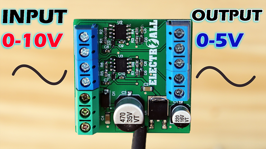
Convertir o reducir una señal digital puede que sea relativamente sencillo, pero convertir una señal analógica pueda que sea un poco mas complicado, ya que dicha señal varia en el tiempo. Pero no se preocupen, hoy aprenderemos a como realizar un circuito conversor de voltaje analógico de 0-10V a un voltaje de 0-5V en corriente continua. Por otro lado, este circuito nos permitirá entender a más detalle el funcionamiento de las entradas analógicas de voltaje del plc v6 que hemos realizado.
ESPECIFICACIONES TÉCNICAS

- Tensión de alimentación……………………….…………12 – 24VDC
- Corriente de alimentación………………….……………25mA
- Entadas Voltaje Analógico..……………………….……4
- Salida Voltaje Analógico..………………………….……4
- Dimensiones……………………………………………………….40x40mm

LISTA DE COMPONENTES ELECTRONICOS
| Categoría | Cantidad | Referencias | Valor | PCB Package | Datasheet |
| Condensadores | 1 | C1 | 220uF | CAP SMD 6.3X7.7MM ALUMINUM 220UF/16V | (see &buy) |
| Condensadores | 2 | C2,C4 | 100nF | 1206_CAP | (see &buy) |
| Condensadores | 1 | C3 | 470uF | CAP SMD 10.5X10MM ALUMINUM 470UF/35V | (see &buy) |
| Condensadores | 6 | C5,C6,C7,C8,C9,C10 | 100nF | 0603_CAP | (see &buy) |
| Resistencias | 8 | R1,R2,R3,R4,R5,R6,R7,R8 | 1k | 0603_RES | (see &buy) |
| Integrados | 1 | U1 | 7812 | DPAK-N | (see &buy) |
| Integrados | 2 | U2,U3 | LM358N | SO8 | (see &buy) |
| Diodos | 1 | D1 | SS14-TP | DIOM5226X230N | (see & buy) |
| Diodos | 4 | D2,D3,D4,D5 | MM3Z5V1T1G | SOD-323 | (see & buy) |
| Miscelánea | 2 | J1,J4 | TBLOCK-M3 | T-BLOCK 3PIN BLUE | |
| Miscelánea | 3 | J2,J3,J5 | TBLOCK-M2 | T-BLOCK 2PIN BLUE |
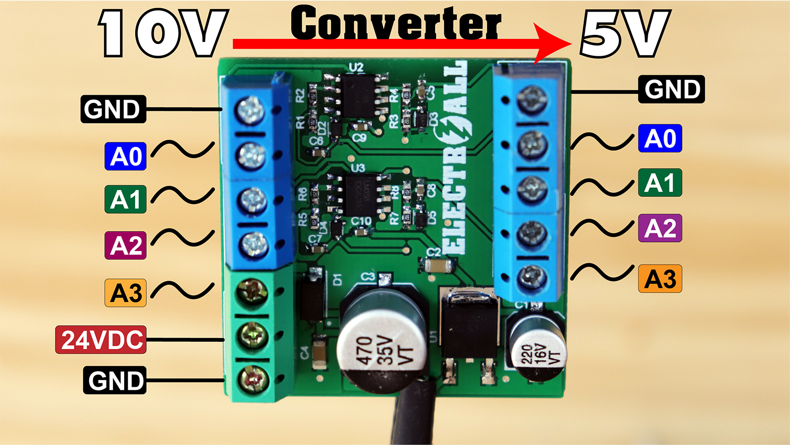
CONEXIONES EXTERNAS
CONEXIONES CON ARDUINO

CÓDIGO DE PRUEBA ARDUINO
int led=13;
void setup() {
  Serial.begin(9600);
pinMode(led,OUTPUT);
}

void loop() {
  int a0 = analogRead(A0);
  int a1 = analogRead(A1);
  int a2 = analogRead(A2);
  int a3 = analogRead(A3);
  Serial.println(a1);
  delay(1000);
if(a1>500)digitalWrite(led,1);
else      digitalWrite(led,0);
}