INTRODUCCIÓN
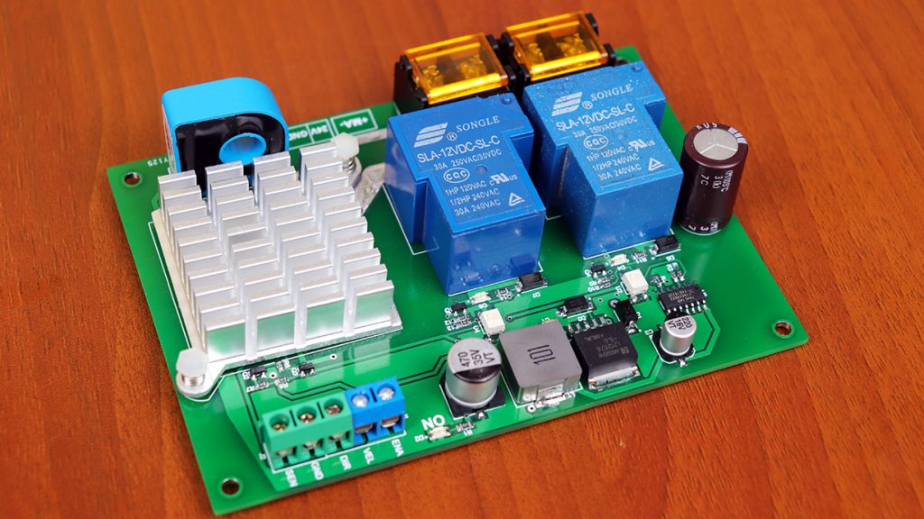
Hace dos años atrás subí un video enseñando a como controlar un motor de corriente continua. Sin embargo, dicho circuito tenia varios inconvenientes. 1), El circuito solo estaba montado en un protoboard. 2) El cambio de la inversión de giro era muy brusco. 3) La velocidad no se controlaba eficientemente. Por último, solo soportaba una cantidad limitada de corriente. Viendo todos estos inconvenientes, en este episodio crearemos una tarjeta PCB capaz de controlar un motor de 24VDC con un consumo hasta de 15A. la inversión de giro se realizará progresivamente “no bruscamente”. Finalmente, tendremos una variación de velocidad eficiente.
ESPECIFICACIONES TÉCNICAS

- Tensión de alimentación……………………….…………24VDC
- Corriente de alimentación………………….……………Depende del consumo del motor
- Entadas digitales nivel TTL 5VDC……………….……3 (ENA, VEL, DIR)
- Salida analógica (sensor corriente “2.5-5V)……..1
- Condiciones ambientales min……………………….….-10°
- Condiciones ambientales max…………………..……….85°
- Empotrable…………………………………………………………Sí
LISTA DE COMPONENTES ELECTRÓNICOS
| Categoría | Cantidad | Referencias | Valor | PCB Package | Datasheet |
| Condensadores | 1 | C1 | 0.1uF | CAPC3216X105 | (see & buy) |
| Condensadores | 1 | C2 | 470uF | CAP SMD 10.5X10MM ALUMINUM 470UF/35V | (see & buy) |
| Condensadores | 1 | C3 | 47uF | CAP SMD 6.3X7.7MM ALUMINUM 220UF/16V | (see & buy) |
| Condensadores | 1 | C4 | 1000uF | ELEC-RAD25 | (see & buy) |
| Resistencias | 3 | R1,R11,R14 | 4.7k | 0805_RES | (see & buy) |
| Resistencias | 5 | R2,R5,R6,R9,R12 | 10k | 0603_RES | (see & buy) |
| Resistencias | 2 | R3,R4 | 220 | 0603_RES | (see & buy) |
| Resistencias | 4 | R7,R8,R10,R13 | 1k | 0603_RES | (see & buy) |
| Resistencias | 3 | R15,R17,R19 | 10k | 0805_RES | (see & buy) |
| Resistencias | 3 | R16,R18,R20 | 1k | 0805_RES | (see & buy) |
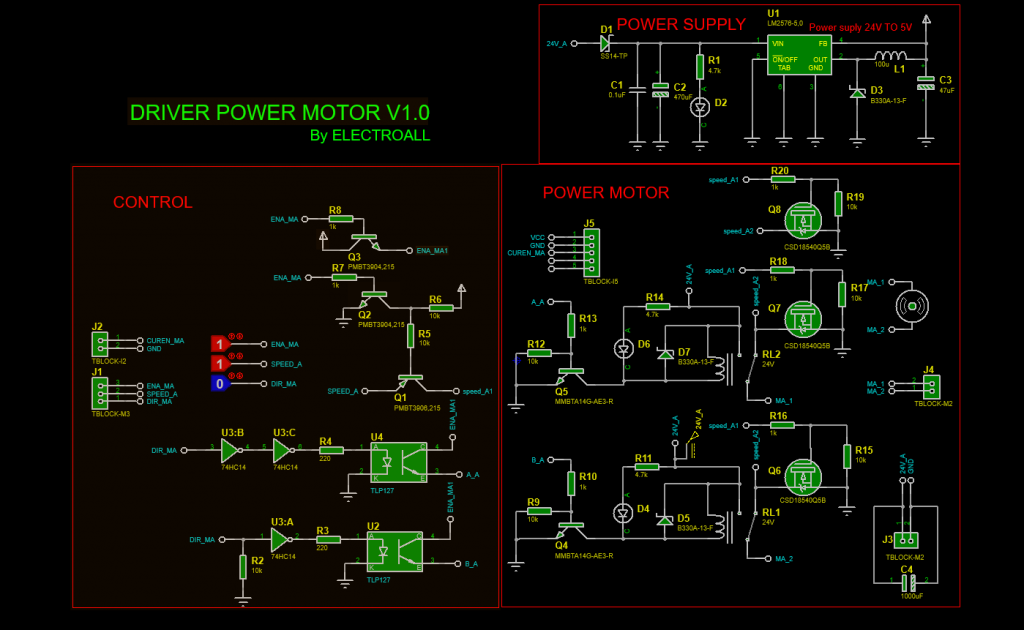
| Integrados | 1 | U1 | LM2576-5,0 | TO170P1410X464-6 | (see & buy) |
| Integrados | 2 | U2,U4 | PC817 | SOIC250P670X300-4 | (see & buy) |
| Integrados | 1 | U3 | 74HC14 | SO14 | (see & buy) |
| Transistores | 1 | Q1 | PMBT3906,215 | SOT23-3 | (see & buy) |
| Transistores | 2 | Q2,Q3 | PMBT3904,215 | SOT23-3 | (see & buy) |
| Transistores | 2 | Q4,Q5 | MMBTA14G-AE3-R | SOT23-3 | (see & buy) |
| Transistores | 3 | Q6,Q7,Q8 | CSD18540Q5B | VSON-CHIP-8 | (see & buy) |
| Diodos | 1 | D1 | SS14-TP | DIOM5226X230N | (see & buy) |
| Diodos | 1 | D2 | LED-GREEN | LEDC3216X110 | (see & buy) |
| Diodos | 3 | D3,D5,D7 | B330A-13-F | DIOM5226X230N | (see & buy) |
| Diodos | 2 | D4,D6 | LED-RED | LEDC3216X110 | (see & buy) |
| Miscelánea | 1 | J1 | TBLOCK-M3 | T-BLOCK 3PIN GREEN | (see & buy) |
| Miscelánea | 1 | J2 | TBLOCK-I2 | T-BLOCK 2PIN BLUE | (see & buy) |
| Miscelánea | 2 | J3,J4 | TBLOCK-M2 | TERMINAL BLOCKS DIBO | (see & buy) |
| Miscelánea | 1 | J5 | TBLOCK-I5 | CURENT SENSOR | (see & buy) |
| Miscelánea | 1 | L1 | 100u | INDUCTOR 100UH | (see & buy) |
| Miscelánea | 2 | RL1,RL2 | 24V | RELAY 24VDC-SL-A | (see & buy) |
PARTES Y CONEXIONES EXTERNAS

DESCRIPCIÓN
- ENA; Este puerto es para poder HABILITAR y DESABILITAR todo el sistema; NIVEL ALTO (5V) “Habilitado, NIVEL BAJO (0V) “Desabilitado”.
- VEL; Por este puerto se regulará la velocidad del motor. En consecuencia, esta entrada admite “PWM” para regular y varear la velocidad del motor
- DIR; Con esta entrada se regulará el sentido de giro del motor; NIVEL ALTO (5V) “Horario”, NIVEL BAJO (0V), Antihorario”.
- GND; GROUND (común)
- SEN; Salida del sensor de corriente (2.5-5V) “2.5V=0A – 5V=15A”
CONEXIONES ARDUINO – MOTOR DRIVER

CÓDIGO ARDUINO
const int in_ena = 2;
const int in_dir = 3;
const int ENA = 8;
const int PWM = 9;
const int DIR = 10;
boolean state_dir = false;
boolean state_slow = false;
boolean state_vel = false;
byte slow = 0;

int valor1 = 0;
int valor2 = 0;

void setup() {
  Serial.begin(9600);
  pinMode(in_ena, INPUT);
  pinMode(in_dir, INPUT);
  pinMode (ENA, OUTPUT);
  pinMode (PWM, OUTPUT);
  pinMode (DIR, OUTPUT);
  digitalWrite(ENA, 0);
  digitalWrite(DIR, 0);

}

void loop() {
  int ana ;
  int map_ana ;
  if (digitalRead(in_ena) == 1 ) digitalWrite(ENA, 1);
  else digitalWrite(ENA, 0);

  if (state_vel == false) {
    ana = analogRead(A0);
    map_ana = map(ana, 0, 1023, 0, 255);
    slow = map_ana;
  }

  if (digitalRead(in_dir) && valor1 == 0 ) {
    delay(100);
    valor2 = 1 - valor2;
  }
  valor1 = digitalRead(in_dir);

if(digitalRead(in_dir)==1){
  if (valor2 == 1) {
    state_vel = true;
    if (state_vel == true) {
      analogWrite(PWM, 0);
      delay(1000);
      digitalWrite(DIR, 1);
      slow=0;
    for(int i=0;i<=map_ana;i++ ){
      slow++;
      delay(10);
      Serial.println(slow);
      analogWrite(PWM, slow);
    }
    if (slow >= map_ana) {
      state_vel = false;
    }
    }
  }
  }

if(digitalRead(in_dir)==1){

   if (valor2 == 0) {
    state_vel = true;
    if (state_vel == true) {
      analogWrite(PWM, 0);
      delay(1000);
      digitalWrite(DIR, 0);
      slow=0;
    for(int i=0;i<=map_ana;i++ ){
      slow++;
      delay(10);
      Serial.println(slow);
      analogWrite(PWM, slow);
    }
    if (slow >= map_ana) {
      state_vel = false;
    }
    }
  }
  }
    analogWrite(PWM, slow);
}